
Ball valve

A ball valve and valve seat technology, which is applied to valve devices, cocks including cut-off devices, mechanical equipment, etc., can solve problems such as ball valve sealing failure, achieve reliable sealing, and avoid valve seat stagnation

Active Publication Date: 2017-11-24
CHNA ENERGY INVESTMENT CORP LTD +1
View PDF9 Cites 1 Cited by
  • Summary
  • Abstract
  • Description
  • Claims
  • Application Information

AI Technical Summary

Problems solved by technology

[0003] The present invention aims to provide a ball valve to solve the problem of ball valve sealing failure in the prior art

Method used


Image

  • Ball valve
  • Ball valve

Examples


Embodiment Construction

[0020] It should be noted that, in the case of no conflict, the embodiments in the present application and the features in the embodiments can be combined with each other. The present invention will be described in detail below with reference to the accompanying drawings and examples.

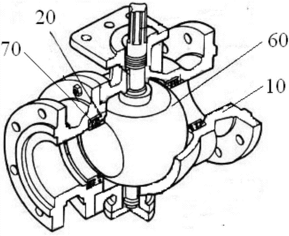
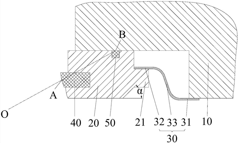
[0021] like figure 1 and figure 2 As shown, the ball valve of this embodiment includes a valve body 10 , a valve seat 20 , a spring 70 and an isolation cylinder 30 . The valve body 10 has an inner cavity, and the valve seat 20 is arranged in the inner cavity. An accommodation space is formed between one end of the valve seat 20 and the valve body 10. The spring 70 is arranged in the accommodation space, and the spring 70 is arranged against the valve body 10 and the valve body. Between the seats 20, the isolation cylinder 30 is connected between the valve body 10 and the valve seat 20, and separates the accommodation space into a spring accommodation space and an overflow space which are ind...


PUM


Abstract

The invention provides a ball valve. The ball valve comprises a valve body (10), a valve seat (20) and a spring (70). The valve body is provided with an inner cavity. The valve seat is arranged in the inner cavity, and a containing space is formed between one end of the valve seat (20) and the valve body (10). The spring is arranged in the containing space, and the spring (70) is arranged between the valve body (10) and the valve seat (20) in an abutting manner. The ball valve further comprises an isolation barrel (30) which is connected between the valve body (10) and the valve seat (20) and divides the containing space into a spring containing space and an overflow space independent of the spring containing space. The spring (70) is contained in the spring containing space. According to the technical scheme, the problem that sealing of a ball valve fails in the prior art is effectively solved.

Description

technical field [0001] The invention relates to the technical field of valves, in particular to a ball valve. Background technique [0002] At present, most of the ball valves used in the coal chemical industry are fixed ball valves. The fixed ball valve includes a valve body, a ball, a valve seat and a spring. The valve seat and the spring are arranged in the inner cavity of the valve body. One end of the spring abuts against the valve body, and the other end of the spring abuts against the valve seat. The valve seat is pressed against the ball by the elastic force of the spring to realize the sealing between the valve body and the ball. However, since there is a gap between the valve body and the valve seat, the solid in the solid-liquid two-phase flow medium easily enters between the valve body and the valve seat. This causes the valve seat to be blocked, the spring loses its effect, and then the seal between the valve body and the ball fails. Contents of the inventio...

Claims


Application Information

Patent Timeline
Patent Type & Authority Applications(China)
IPC IPC(8): F16K5/06F16K5/08
CPCF16K5/06F16K5/08
Inventor 林晖董栗英王军光庄殿升高洪坤
Owner CHNA ENERGY INVESTMENT CORP LTD
Learn More