Desk top clamp

A fixture and angle technology, applied in mechanical equipment, supporting machines, etc., can solve the problems of small occupied space, relying on hardware tools, troublesome use, etc., to achieve the effect of convenient installation and adjustment, convenient adjustment, and avoid repeated operation.

Pending Publication Date: 2017-11-24
KUNSHAN HONGJIE ELECTRONICS CO LTD
View PDF7 Cites 8 Cited by
  • Summary
  • Abstract
  • Description
  • Claims
  • Application Information

AI Technical Summary

Problems solved by technology

[0002] At present, electronic devices such as monitors are positioned on the desktop through brackets. At present, desktop display brackets are mainly realized by means of support support, bolt connection and clamping device clamping. The clamping device clamping mode can Stable positioning, small space occupation, no damage to the desktop, and the ability to change positions at will are popular with everyone. However, the current clamping device generally consists of fixed parts and movable parts, both of which are L-shaped structures, and the side wall of the fixed part is set Several perforations, four threaded holes are set on one side wall of the movable part, the connection between the fixed part and the movable part is realized through bolts, and the distance between the fixed part and the other side wall of the movable part is adjusted through the correspondence of different hole positions to adapt to the Clamping of desktops with different thicknesses requires the use of special tools such as screwdrivers and wrenches for repeated operations during installation and adjustment of this structure, which is time-consuming and requires hardware tools, which is cumbersome and time-consuming to use

Method used


Image

  • Desk top clamp
  • Desk top clamp
  • Desk top clamp

Examples


Embodiment

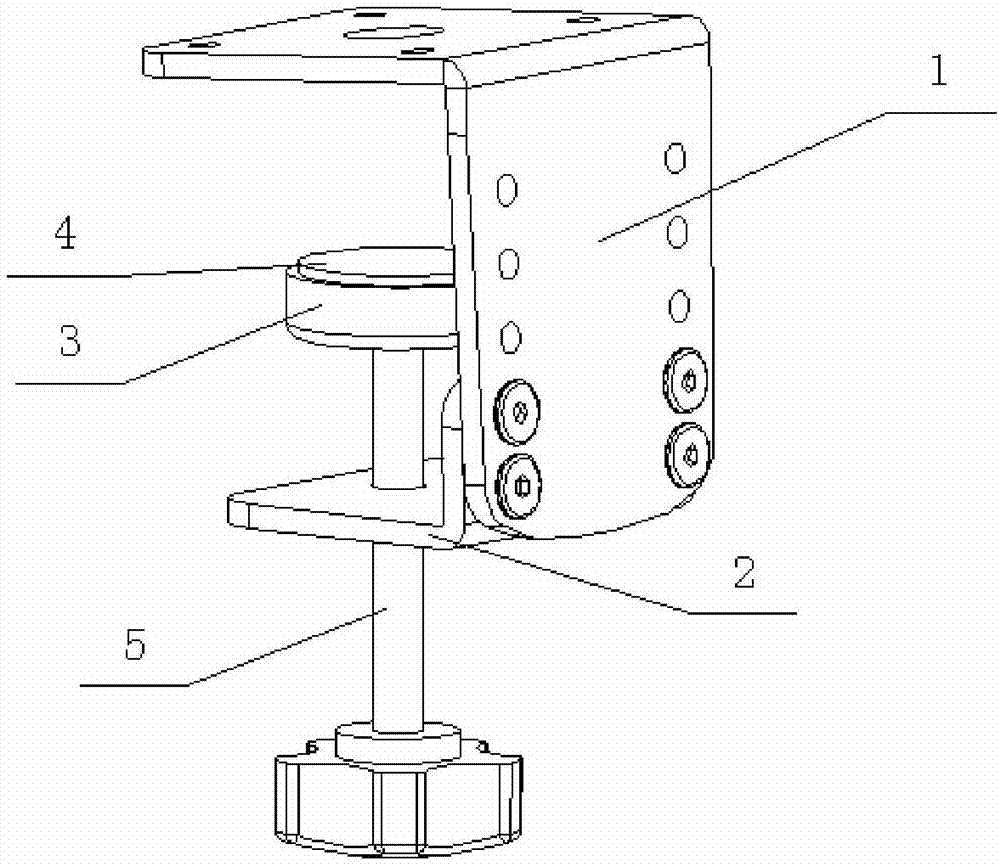
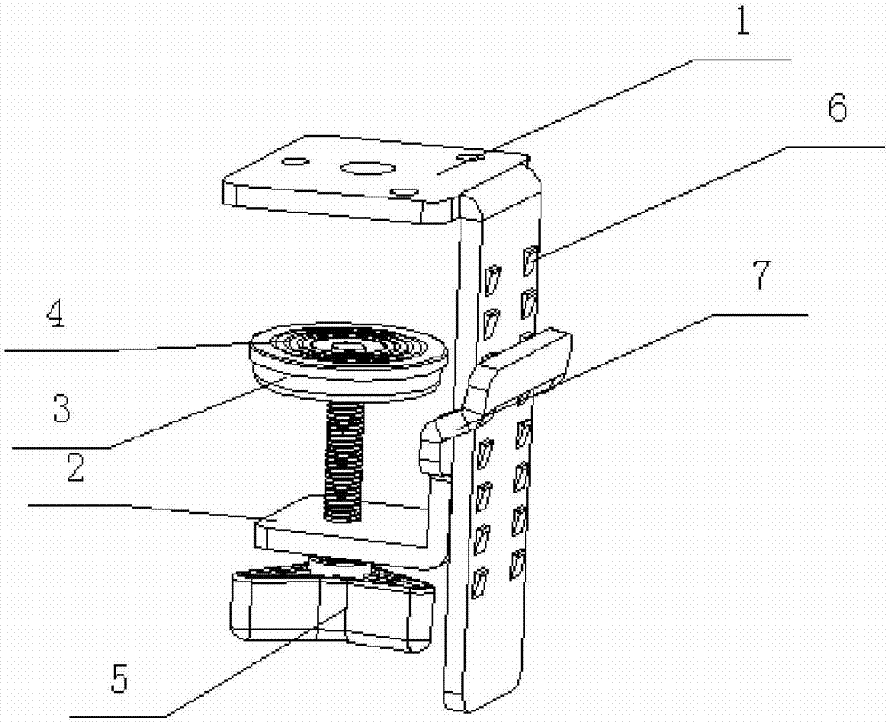
[0041] Embodiment: A desktop fixture, including a fixed part 1 and a movable part 2, the side wall of the movable part 2 is detachably fixedly connected with the side wall of the fixed part 1, and the other side wall of the movable part 2 is connected with the fixed part 1 A clamping space is formed between the other side walls, and the different connection positions between the side wall of the movable part 2 and the side wall of the fixed part 1 realize the adjustment of the distance between the movable part 2 and the fixed part 1, through the fixed part 1 The connection with different positions of the side wall of the movable part 2 realizes the adjustment of the distance between the other side wall of the two, and then realizes the clamping of desktops with different thicknesses. The desktop fixture can also be equipped with a top pad 3 and a top pad lifting drive device The top pad is positioned on the other side wall of the movable part 2 so as to be able to slide towards...


PUM


Abstract

The invention discloses a desk top clamp which comprises a fixed part and a movable part. One side wall of the movable part and one side wall of the fixed part can be detachably fixed and connected together, a clamping space is formed between the other side wall of the movable part and the other side wall of the fixed part, and the adjustment of the distance between the movable part and the fixed part is achieved through different connecting positions for one side wall of the movable part and one side wall of the fixed part. Rapid connection and separation of the fixed part and the movable part are achieved by arranging first and second fasteners on one side wall of the fixed part and one side wall of the movable respectively, repeated bolt operation through hardware tools is avoided, the clamping space between the other side wall of the fixed part and the other side of the movable part is convenient to adjust, time and labor are saved, and the desk top clamp does not depend on hardware tools and is more convenient to install and adjust.

Description

technical field [0001] The invention relates to a clamping device, in particular to a desktop clamp. Background technique [0002] At present, electronic devices such as monitors are positioned on the desktop through brackets. At present, desktop display brackets are mainly realized by means of support support, bolt connection and clamping device clamping. The clamping device clamping mode can Stable positioning, small space occupation, no damage to the desktop, and the ability to change positions at will are popular with everyone. However, the current clamping device generally consists of fixed parts and movable parts, both of which are L-shaped structures, and the side wall of the fixed part is set Several perforations, four threaded holes are set on one side wall of the movable part, the connection between the fixed part and the movable part is realized through bolts, and the distance between the fixed part and the other side wall of the movable part is adjusted through t...

Claims


Application Information

Patent Timeline
Patent Type & Authority Applications(China)
IPC IPC(8): F16M13/02
CPCF16M13/02F16M2200/08
Inventor 常晓杰
Owner KUNSHAN HONGJIE ELECTRONICS CO LTD
Why Eureka
Try Eureka