High-speed super-resolution stationary point scanning imaging method based on wavenumber domain coherence factor

A coherence factor and super-resolution technology, applied in the field of synthetic aperture imaging algorithm, can solve the problem of non-existence of super-resolution imaging algorithm

Active Publication Date: 2019-06-14
JILIN UNIV
View PDF2 Cites 0 Cited by
  • Summary
  • Abstract
  • Description
  • Claims
  • Application Information

AI Technical Summary

Problems solved by technology

For real-time imaging systems, there are no super-resolution imaging algorithms available yet

Method used


Image

  • High-speed super-resolution stationary point scanning imaging method based on wavenumber domain coherence factor
  • High-speed super-resolution stationary point scanning imaging method based on wavenumber domain coherence factor
  • High-speed super-resolution stationary point scanning imaging method based on wavenumber domain coherence factor

Examples


Embodiment 1

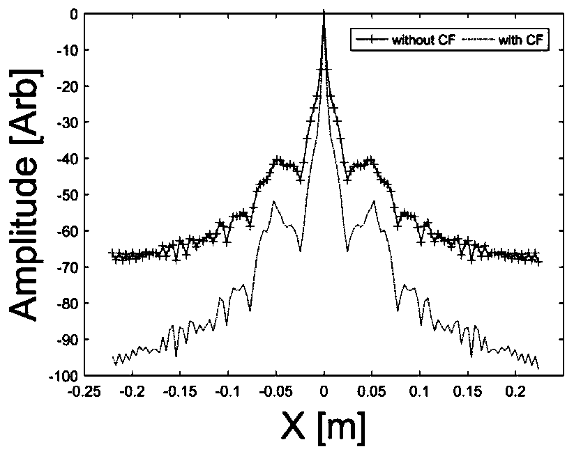
[0098] Example 1: Point Spread Function

[0099] In this embodiment, the point spread function performances of the traditional RMA and the coherence factor RMA imaging algorithms are respectively calculated. The main parameters used for the calculations are listed in Table 1.

[0100] Table 1 The main parameters used in the calculation of point extension function

[0101]

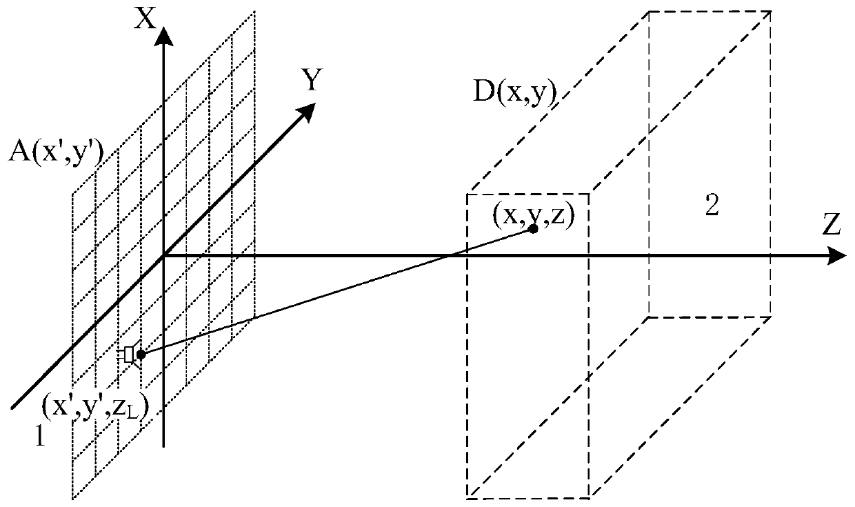
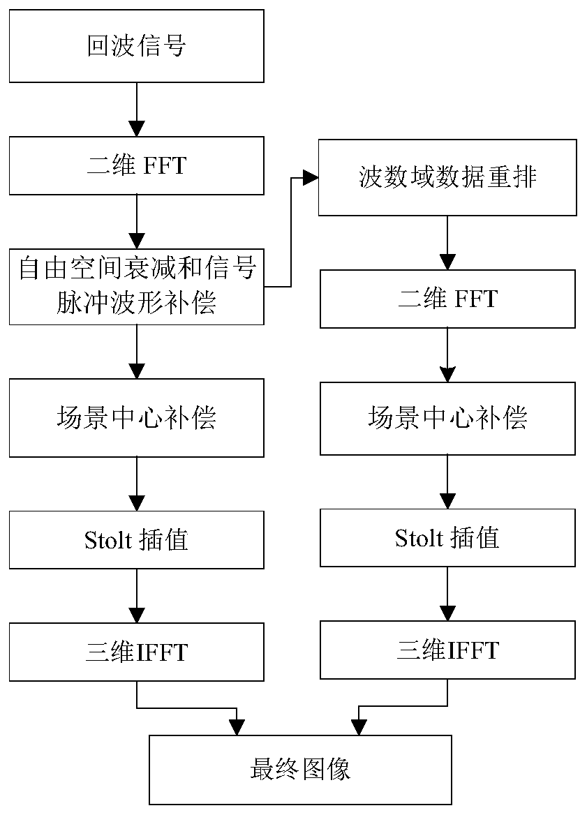
[0102] The point spread function is to adopt the ideal point target, generate the echo signal by the signal model of SA, and use the imaging algorithm to obtain the image of the point target. Depend on figure 2 As shown, the detailed steps of coherence factor RMA are as follows:

[0103] Step 1: The antenna receives and records the echo signal;

[0104] Step 2: Reflectance calculation.

[0105] This step actually uses RMA to directly reconstruct the 3D image of the target, mainly including the following steps:

[0106] Step 2.1: Perform two-dimensional FFT on the echo signal;

[0107] Step 2.2: f...

Embodiment 2

[0131] Embodiment 2: Electromagnetic Simulation Imaging

[0132] This embodiment is mainly used to verify the imaging performance of the coherence factor RMA for continuous targets. The main parameters used in the simulation are shown in Table 1, the only difference is that the values ​​of the α and β parameters are different, namely α=1.5, β=0.00375.

[0133] Simulation consists of two steps:

[0134] Step 1: Using the method of moments to generate the scattered field of the target as echo data;

[0135] Imaging objects such as Figure 5 Shown is a two-dimensional model of an eight-leaf fan-shaped ideal electric conductor. The electromagnetic simulation uses a Hertzian electric dipole source, the source and the point detector are located at the same location, and only the electric field polarized in the same direction is considered.

[0136] Step 2: The echo data is processed by traditional RMA and coherence factor RMA respectively, and the image reconstruction is complet...

Embodiment 3

[0138] Embodiment 3: Imaging experiment results

[0139] In this embodiment, the performance of the coherence factor RMA is verified by a single-antenna stationary-point scanning imaging experiment. The experimental platform consists of two parts, namely the scanning platform and the vector network analyzer. The scanning platform is used to translate the sample to be imaged according to the prescribed method, allowing to define the moving range and moving step in the two dimensions of the plane; the vector network analyzer (Agilent, N5247A) is used to generate, transmit and receive echo signals, due to The instrument structure is coherent, so there is no need to correct the waveform of the carrier, and the sampled data S11 or S22 can be processed directly.

[0140] The imaging target is an eight-leaf metal sector, such as Figure 8 shown. The target body is fixed on the scanning platform, and the parameters of the experiment are listed in Table 3.

[0141] Table 3 Experime...


PUM


Abstract

The present invention discloses a wave number domain coherence factor-based high-speed super-resolution stagnation point scanning imaging method. The method specifically includes the following steps that: step 1, an antenna receives and records echo signals; step 2, a reflectance function is calculated; step 3, a coherence factor is calculated; and step 4, the coherent factor is used to correct an image. According to the algorithm of the invention, the concept of the space-domain coherence factor is expanded to the wave number domain, and a distance migration imaging algorithm is used in combination, and therefore, the method can have real-time imaging capacity; and if combined with a parallel algorithm, the method can further improve efficiency. Compared with a traditional distance migration imaging algorithm and back-projection imaging algorithm, the wave number domain coherence factor-based high-speed super-resolution stagnation point scanning imaging method has higher resolution and lower side lobe and can effectively suppress base noises. Since parameters alpha and beta are adopted to adjust the performance of the coherence factor, and the suppression of the coherence factor on side lobe and weak scattering points can be balanced, and therefore, performance is stable.

Description

technical field [0001] The invention relates to a synthetic aperture imaging algorithm, in particular to a high-speed super-resolution stationary point scanning imaging method based on wave number domain coherence factors. Background technique [0002] Synthetic Aperture (SA) imaging algorithm is the most widely used radar imaging technology at present. The characteristic of this technology is based on the pulse compression technology. Compared with the traditional electromagnetic imaging method, the calculation amount is smaller and the memory requirement is smaller. Low and is the method of choice for real-time imaging systems. SA adopts a Born-approximated electric field signal model. In order to ensure the accuracy of the image, no far-field approximation is considered. The two most classic SA imaging methods are backprojection imaging algorithm (BPA) and distance migration imaging algorithm. (range migration algorithm, RMA). Both methods have their own characteristics...

Claims


Application Information

Patent Timeline
Patent Type & Authority Patents(China)
IPC IPC(8): G01S13/90
CPCG01S13/90G01S13/9011G01S13/9017
Inventor 郭企嘉常天英崔洪亮
Owner JILIN UNIV
Why Eureka
Try Eureka