
Combined type sealing device for rotary shaft

A sealing device and a combined technology, which is applied in the direction of engine sealing, engine components, mechanical equipment, etc., can solve problems such as poor sealing performance, achieve stable sealing performance, prolong the life of the sealing device, and avoid wear and tear

Active Publication Date: 2017-11-28
HEFEI HENGDAJIANGHAI PUMP IND CO LTD
View PDF2 Cites 4 Cited by
  • Summary
  • Abstract
  • Description
  • Claims
  • Application Information

AI Technical Summary

Problems solved by technology

[0004]In order to overcome the above-mentioned technical problems, the object of the present invention is to provide a combined sealing device for the rotating shaft, through the cooperative design of the sealing ring and the sealing seat, the When the rotating shaft is not rotating or at low speed, the horn-shaped sealing ring can reliably ensure the sealing performance, which solves the problem of poor sealing performance between the moving ring and the static ring at low speed; The space effectively guarantees the lubrication environment of the moving ring and the static ring, so this combined sealing device can prolong the service life of the sealing device and enhance the sealing performance at the same time

Method used


Image

  • Combined type sealing device for rotary shaft
  • Combined type sealing device for rotary shaft
  • Combined type sealing device for rotary shaft

Examples


Embodiment Construction

[0027] The following will clearly and completely describe the technical solutions in the embodiments of the present invention with reference to the accompanying drawings in the embodiments of the present invention. Obviously, the described embodiments are only some, not all, embodiments of the present invention. Based on the embodiments of the present invention, all other embodiments obtained by persons of ordinary skill in the art without creative efforts fall within the protection scope of the present invention.

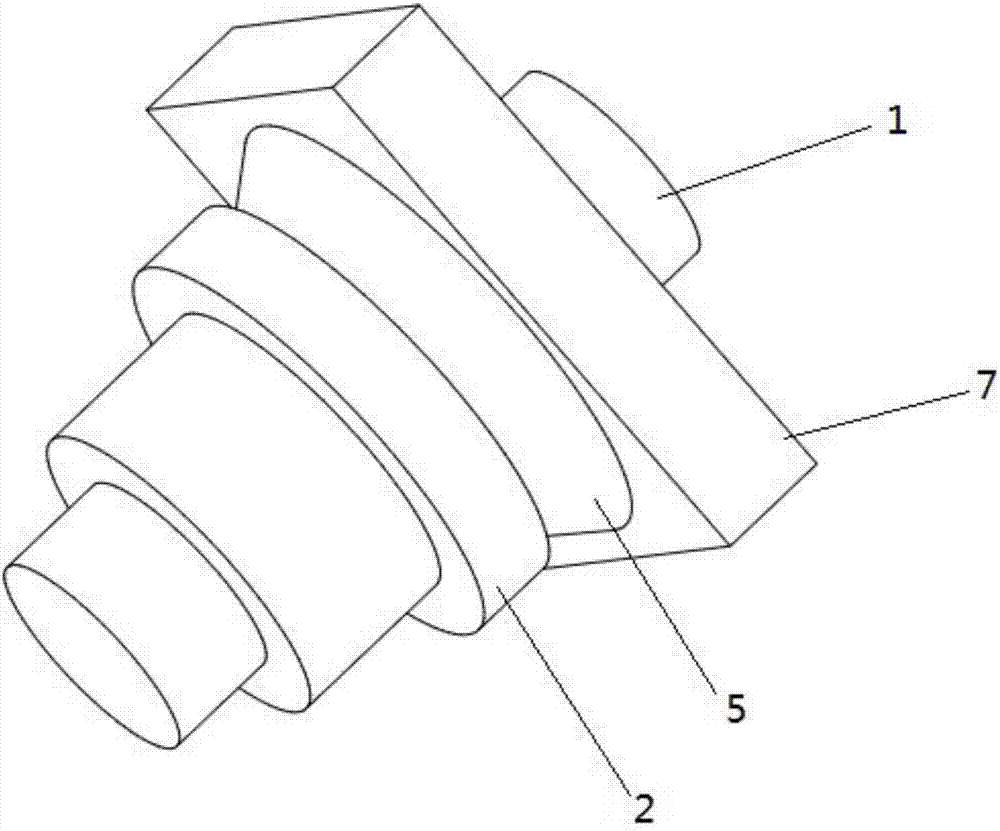
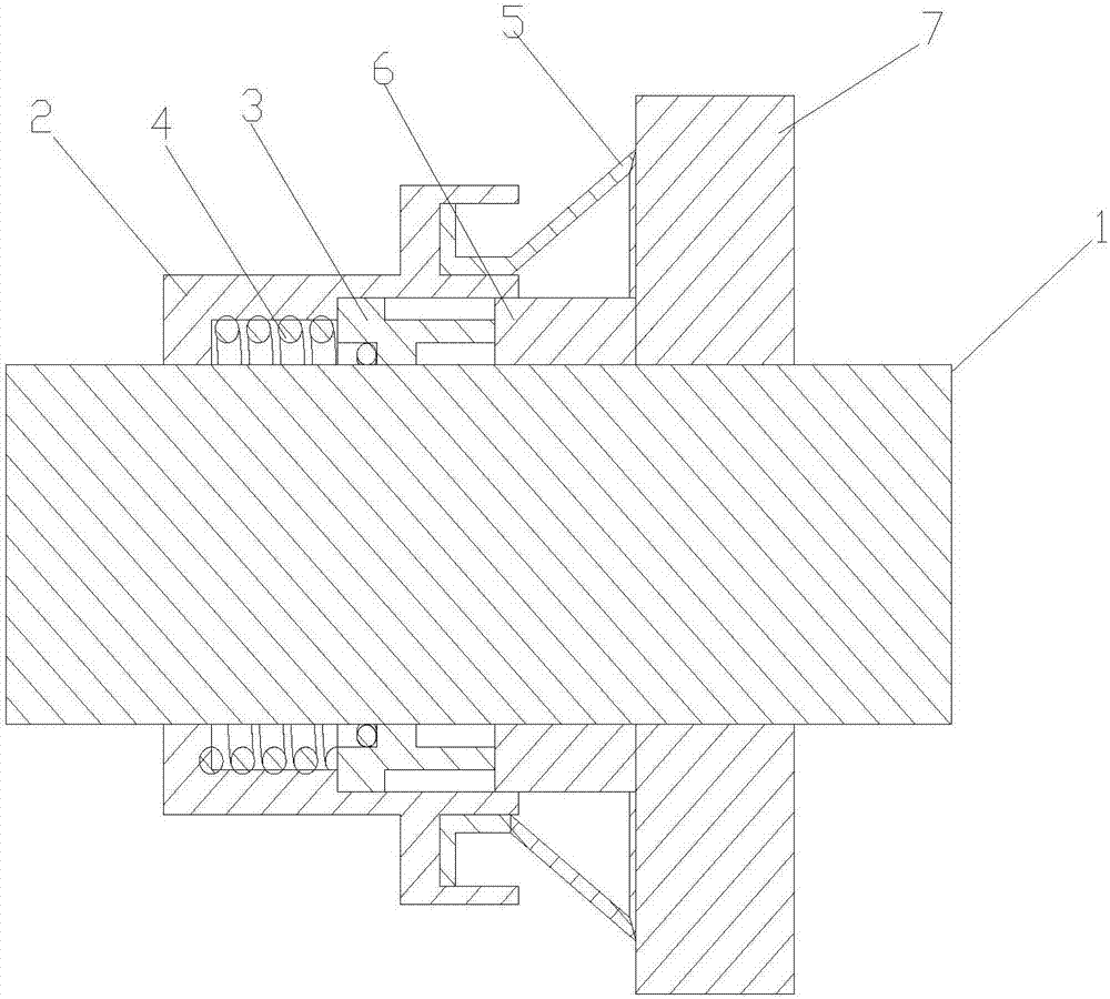
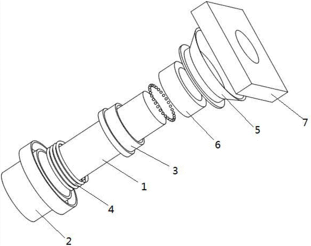
[0028] Such as figure 1 , figure 2 and image 3 As shown, a combined sealing device for a rotating shaft includes a rotating shaft 1, and one end of the rotating shaft 1 is interference-fitted with a moving ring seat 2 and a moving ring 3, and the moving ring seat 2 and the moving ring 3 are connected by a compression spring 4 , the moving ring seat 2 is fastened and fixed with a sealing ring 5, and the other end of the shaft 1 is sealed and rotated with a stati...


PUM


Abstract

The invention discloses a combined type sealing device for a rotary shaft. The combined type sealing device comprises the rotary shaft. One end of the rotary shaft is in interference fit with a moving ring seat and a moving ring. The moving ring seat is connected with the moving ring through a compressed spring. A sealing ring is clamped and fixed in the moving ring seat. The other end of the rotary shaft is rotationally matched with a static ring and a sealing seat in a sealing mode. The static ring is attached and fixed to the outer end of the sealing seat and located inside the sealing ring. According to the combined type sealing device for the rotary shaft, through the matched design of the sealing ring and the sealing seat, the horn-shaped sealing ring can reliably guarantee the leakproofness under the condition that the rotary shaft does not rotate or rotates at a low speed, and the problem that the sealing performance of the moving ring and the static ring is poor at the low speed is solved; and then through a wedge-shaped space formed between the horn-shaped sealing ring and the sealing seat, the lubrication environment of the moving ring and the static ring is effectively guaranteed, in this way, according to the combined type sealing device, the service life of the sealing device can be well prolonged, and meanwhile, the sealing performance is improved.

Description

technical field [0001] The invention belongs to the field of mechanical manufacturing, and in particular relates to a sealing device, more specifically to a combined sealing device for a rotating shaft. Background technique [0002] A mechanical seal is a shaft seal device for a rotating machine. Such as centrifugal pumps, centrifuges, reactors and compressors and other equipment. Since the transmission shaft runs through the inside and outside of the equipment, there is a circumferential gap between the shaft and the equipment, and the medium in the equipment leaks outward through this gap. If the pressure inside the equipment is lower than the atmospheric pressure, the air leaks into the equipment, so there must be a Shaft seal to prevent leakage. There are many types of shaft seals. Because mechanical seals have the advantages of less leakage and long life, mechanical seals are the most important shaft sealing method in these equipments in the world today. The mechanic...

Claims


Application Information

Patent Timeline
IPC IPC(8): F16J15/34F16J15/3284
CPCF16J15/3284F16J15/3404
Inventor 李星荚小健王诚成舒雪辉钱凤辉
Owner HEFEI HENGDAJIANGHAI PUMP IND CO LTD
Learn More