

Mechanism for automatically mounting complete set of LED light bars
An LED light bar and automatic completion technology, applied in the field of mechanical installation, can solve problems such as low operating efficiency
- Summary
- Abstract
- Description
- Claims
- Application Information
AI Technical Summary
Problems solved by technology
Method used
Image

Examples
Embodiment Construction
[0018] The present invention will be specifically introduced below in conjunction with the accompanying drawings and specific embodiments.
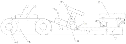
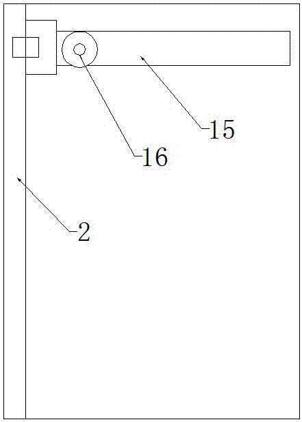
[0019] A mechanism for automatically completing the installation of a complete set of LED light strips 4, including: a conveyor belt 6 component that transmits the LED light strip 4 wrapped with a plastic film 3, a separation partition component that separates the LED light strip 4 from the plastic film 3, and receives the detached plastic film 3 The angle conversion component of the LED light bar 4 receives the angle-converted LED light bar 4 and places the workbench 1 of the installation frame, and the first guide rail 2 on the workbench 1 is connected to the first guide rail 2 and the LED light The bar 4 is sucked to the vacuum suction cup 14 above the mounting frame, connected to the first guide rail 2 and pressing the LED light bar 4 into the pressing assembly in the mounting frame.
[0020] The assembly of the conveyor belt 6 consis...
PUM
 Abstract
Description
Claims
Application Information