Eyeglasses-type display apparatus
A display device, glasses-type technology, applied in the direction of equipment, TV, color TV parts, etc., can solve the problem that the image is not easy to visually confirm, and achieve the effect of high-precision adjustment
- Summary
- Abstract
- Description
- Claims
- Application Information
AI Technical Summary
Problems solved by technology
Method used
Image

Examples
no. 1 Embodiment approach
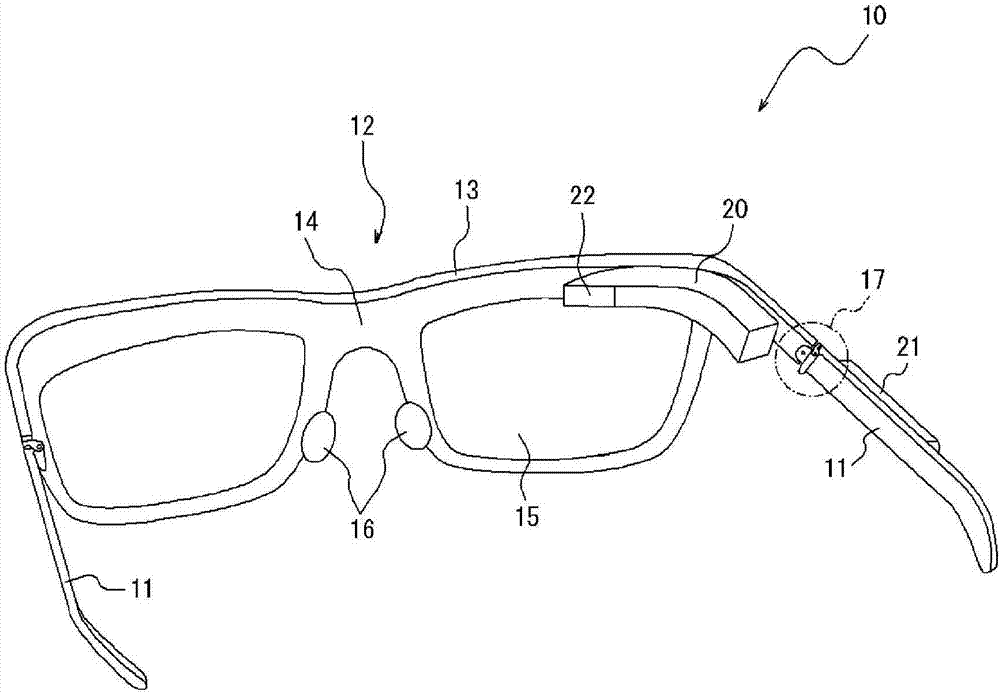
[0051] figure 1It is a perspective view of the glasses-type display device 10 according to the first embodiment of the present invention, viewed from the back side of the glasses. The glasses-type display device 10 includes: a glasses portion configured to include left and right temple portions 11 and a glasses front portion 12 ; and an image display unit 20 . The temple portion 11 is used to hang the user's ear to wear the glasses-type display device 10 similarly to ordinary glasses. The front part 12 of the glasses is the front part of the glasses placed in front of the user's eyes, and includes left and right frame parts 13 , bridge parts 14 , left and right lenses 15 , and left and right nose pads 16 . The left and right frame portions 13 respectively hold the left and right lenses 15 so as to surround the left and right lenses 15 . Furthermore, the bridge portion 14 is located at the center of the left and right frame portions 13 surrounding the left and right lenses 15...
no. 2 Embodiment approach
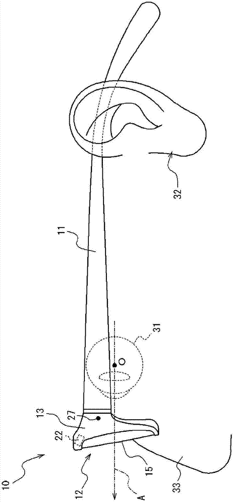
[0062] In addition, in the above-mentioned first embodiment, the position adjustment of the eyepiece optical part 22 is performed only by rotating the front part 12 of the glasses with respect to the temple part 11 . On the other hand, referring again to Image 6 with Figure 7 Also, by moving the eyepiece optical portion 22 back and forth or up and down without changing the orientation of the eyepiece optical portion 22 , it is possible to improve the visual recognition state of the displayed image. For example, by Image 6 Without changing the direction of the eyepiece optical part 22, the eyepiece optical part 22 is moved horizontally toward the eyeball 31 side, so that the outgoing light L can pass through the center O of the eyeball. Or by shifting the eyepiece optical portion 22 upward without changing the orientation of the eyepiece optical portion 22 , it is also possible to make the emitted light beam L pass through the center O of the eyeball. In the second embodi...
no. 3 Embodiment approach
[0066] Figure 10It is a diagram showing a state where a user wears the glasses-type display device 10B according to the third embodiment. Furthermore, this glasses-type display device 10B is also different from the glasses-type display device 10 of the first embodiment in the temple portion 42 . The temple portion 42 is composed of a first portion 42a, a second portion 42b, and a third portion 42c in this order from the glasses front portion 12 side. A first rotation shaft 43a is provided between the first part 42a and the second part 42b, and the first part 42a and the second part 42b are connected so as to be rotatable within a predetermined range about the first rotation shaft 43a. In addition, a second rotation shaft 43b is provided between the second portion 42b and the third portion 42c, and the second portion 42b and the third portion 42c are rotatable within a predetermined range around the second rotation shaft 43b. connect. Since other configurations are the same...
PUM
 Abstract
Description
Claims
Application Information
 - R&D
- Intellectual Property
- Life Sciences
- Materials
- Tech Scout
- Unparalleled Data Quality
- Higher Quality Content
- 60% Fewer Hallucinations
Browse by: Latest US Patents, China's latest patents, Technical Efficacy Thesaurus, Application Domain, Technology Topic, Popular Technical Reports.
© 2025 PatSnap. All rights reserved.Legal|Privacy policy|Modern Slavery Act Transparency Statement|Sitemap|About US| Contact US: help@patsnap.com