Bypass type piezoelectric type inner guide fuel gas injection valve with floating valve seat

A technology of gas injection valve and floating valve seat, which is used in engine components, combustion engines, machines/engines, etc., can solve problems such as affecting the normal use of the engine, engine performance, reverse leakage of the injection valve, insufficient gas supply, etc., to avoid Air flow interference, the effect of realizing the stability of the gas path, ensuring reliability and safety

Active Publication Date: 2017-12-01
HARBIN ENG UNIV
View PDF9 Cites 0 Cited by
  • Summary
  • Abstract
  • Description
  • Claims
  • Application Information

AI Technical Summary

Problems solved by technology

At present, natural gas engines often have insufficient gas supply when working under full working conditions, resulting in unstable speed when the engine is running under full working conditions, which will be more serious on high-power engines, which seriously affects the normal use of the engine and engine performance
In the case of severe engine operating conditions, the injection valve is prone to reverse leakage

Method used


Image

  • Bypass type piezoelectric type inner guide fuel gas injection valve with floating valve seat
  • Bypass type piezoelectric type inner guide fuel gas injection valve with floating valve seat
  • Bypass type piezoelectric type inner guide fuel gas injection valve with floating valve seat

Examples


Embodiment Construction

[0018] The present invention is described in more detail below in conjunction with accompanying drawing example:

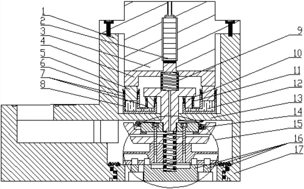
[0019] combine Figure 1-7 , figure 1 It is a schematic diagram of the overall structure of the bypass-type inner-guided gas injection valve with floating valve seat 17 of the present invention, which is mainly composed of piezoelectric actuator 3, main return spring 14, auxiliary return spring 9, valve core assembly 15, valve body 1 and Floating valve seat 17 forms. The piezoelectric actuator 3 is fixed on the valve body 1 by fixing bolts, and a valve core assembly 15 and a floating valve seat 17 are sequentially arranged below the piezoelectric actuator 3 from top to bottom.

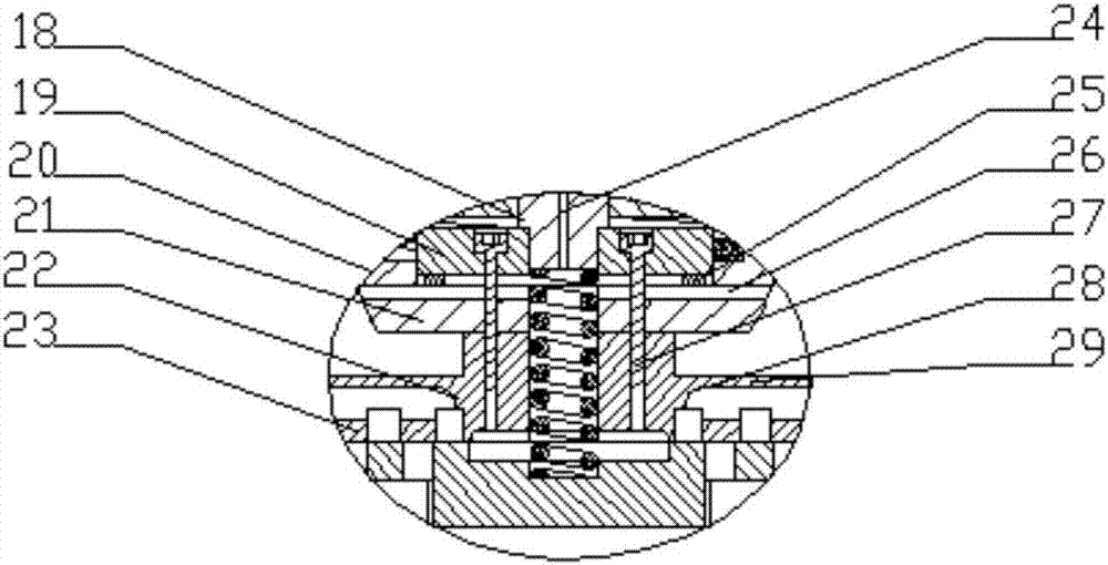
[0020] Such as figure 2 As shown, a valve core assembly 15 of a bypass type piezoelectric internally guided gas injection valve with a floating valve seat is mainly composed of a guide pin 18, an armature 19, a spring seat 20, a fastening bolt 27, a gasket 25, and a bottom plate 21 an...


PUM


Abstract

The invention aims at providing a bypass type piezoelectric type inner guide fuel gas injection valve with a floating valve seat. Through the floating valve seat structure, reverse leakage caused by imbalance of the internal and external pressure of a fuel gas injection valve is avoided, and the working reliable of the fuel gas injection valve is guaranteed. The gas intake and flow guide process is realized through a bypass structure and a flow guide cavity structure. A valve element and a gas circuit are controlled through a piezoelectric actuator to realize the function of gas injection of the fuel gas valve. Through matching of an inner guide structure, pressure balance holes and pressure balance slots, the perpendicularity of the valve element is guaranteed, the work stability and reliable of gas flow are realized, and the response speed is high. The mixed gas intake mode of direct gas intake through an axial main gas slot and gas intake through circumferential gas make-up holes, the large flow is realized, and the gas supply efficiency of an engine is effectively improved; meanwhile, gas flow interference can be avoided, and the stability of the gas circuit is realized; and through multiple ring band structures between the valve element and the valve seat, surface sealing and high stability of the fuel gas injection valve are realized.

Description

technical field [0001] The invention relates to a gas injection valve, in particular to a gas injection valve for a natural gas engine. Background technique [0002] In recent years, with the rapid growth of my country's oil consumption, oil is heavily dependent on imports. Natural gas burns cleanly and has abundant reserves in my country, making it the most likely fuel to replace diesel. Natural gas engines have good application prospects as ship power, especially as propulsion power for inland watercraft. As a fuel supply device for a natural gas engine, the performance of the gas injection valve directly determines the economy and emission performance of the natural gas engine. At present, natural gas engines often have insufficient gas supply when working under full working conditions, resulting in unstable speed when the engine is running under full working conditions, which will be more serious on high-power engines, which seriously affects the normal use of the engi...

Claims


Application Information

Patent Timeline
Patent Type & Authority Applications(China)
IPC IPC(8): F02M21/02
CPCF02M21/0248F02M21/0254F02M21/026Y02T10/30
Inventor 刘鹏范立云彭文博蒋顺浩王德玉王鑫王毓源
Owner HARBIN ENG UNIV
Why Eureka
Try Eureka