High-performance multi-channel rotary joint for water

A rotary joint and multi-channel technology, applied in the direction of pipe components, etc., can solve the problem of easy wear of seals, and achieve the effect of reducing the probability of wear failure

Pending Publication Date: 2017-12-01
GENERAL ENG RES INST CHINA ACAD OF ENG PHYSICS
View PDF6 Cites 8 Cited by
  • Summary
  • Abstract
  • Description
  • Claims
  • Application Information

AI Technical Summary

Problems solved by technology

[0004] The purpose of the present invention is to propose a high-performance multi-channel water rotary joint with high pressure, high speed and long life for the problem that the seals of the traditional contact-type sealed rotary joint are easy to wear

Method used


Image

  • High-performance multi-channel rotary joint for water
  • High-performance multi-channel rotary joint for water
  • High-performance multi-channel rotary joint for water

Examples


Embodiment Construction

[0030] The present invention will be further described below in conjunction with accompanying drawing:

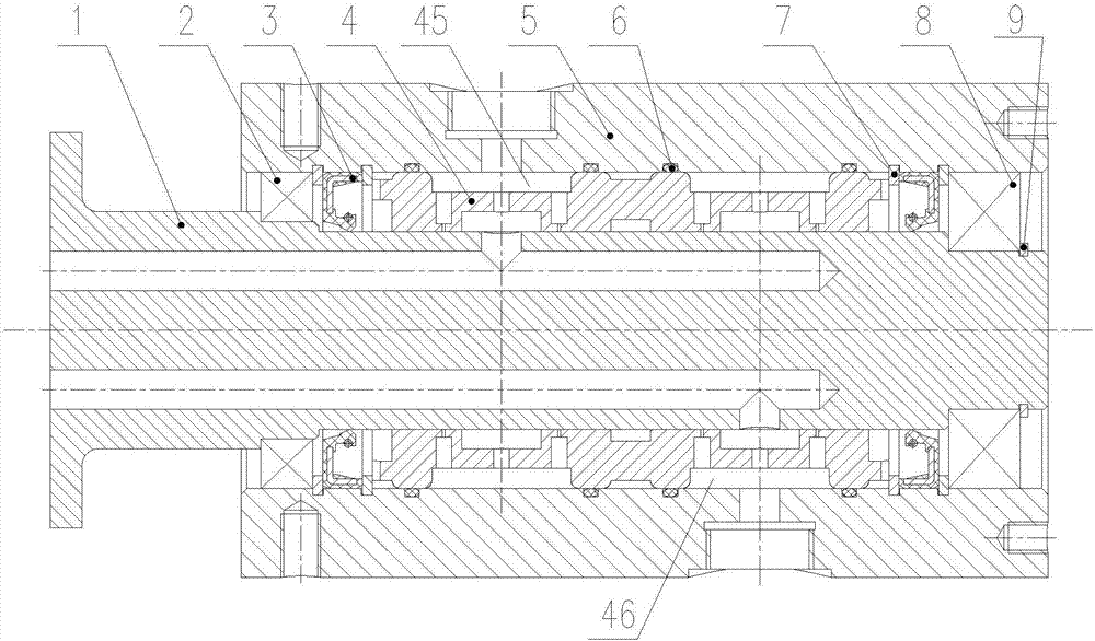
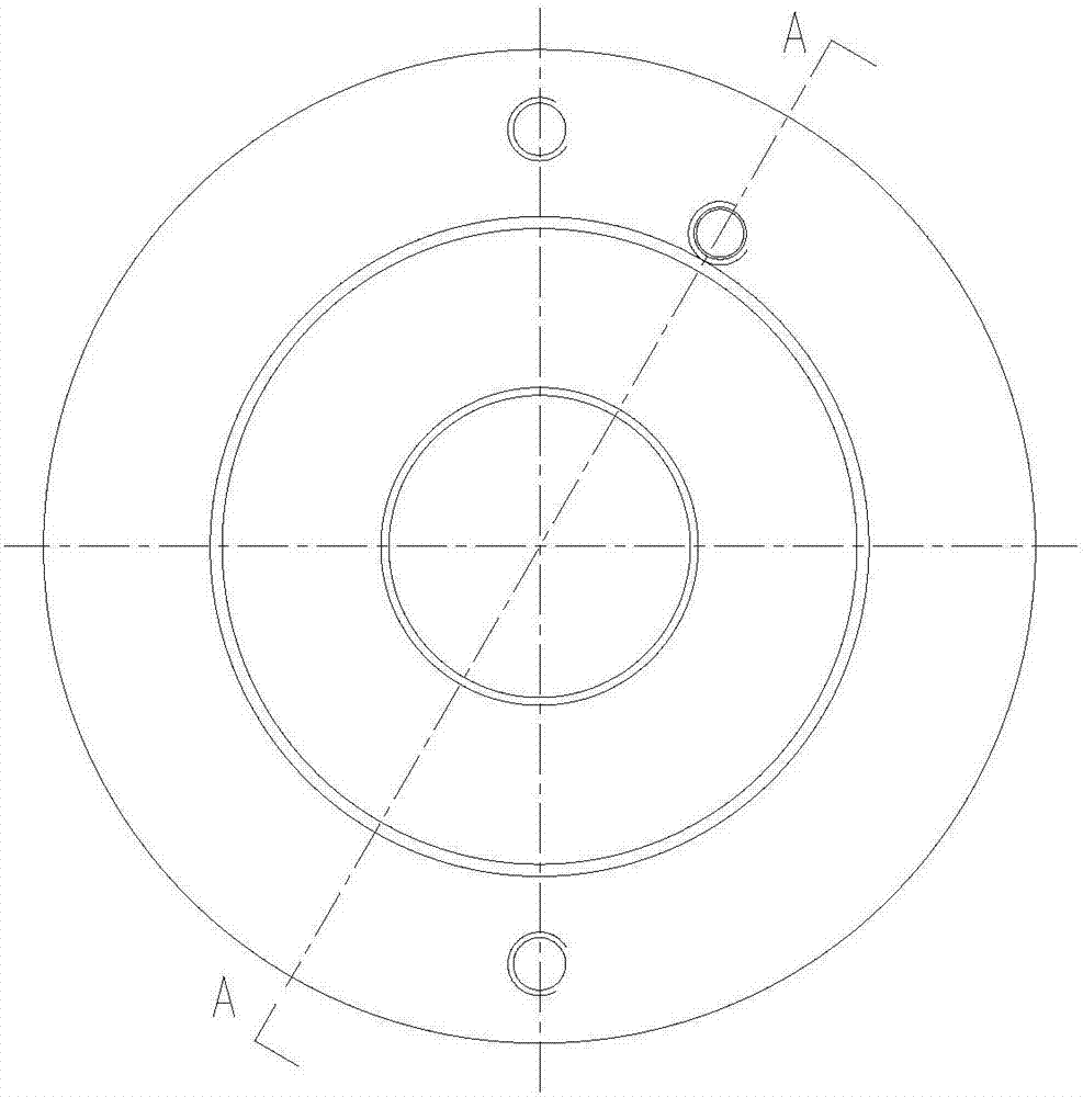
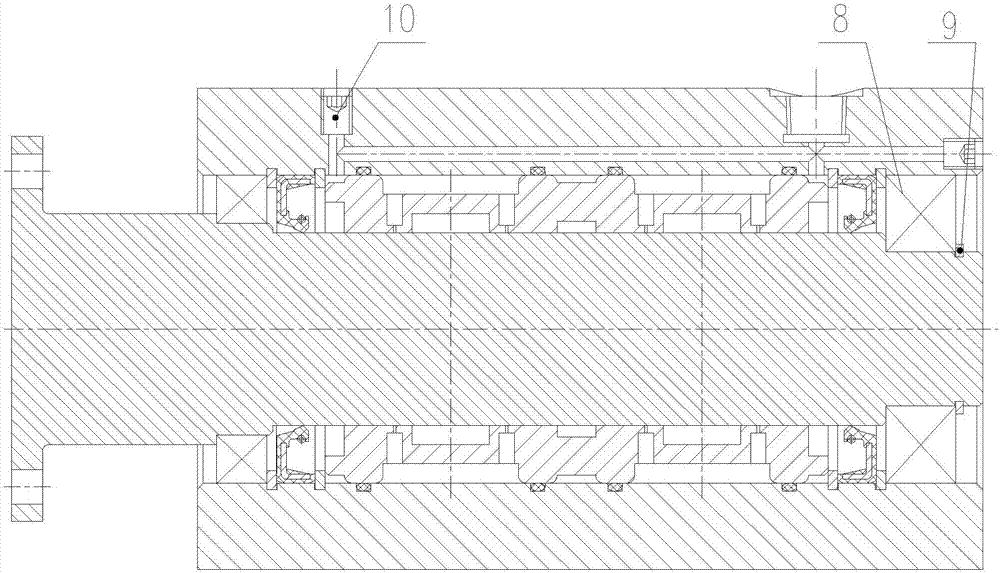
[0031] combine figure 1 , figure 2 , image 3 , Figure 4 , Figure 5 , Figure 6 , Figure 7 , Figure 8 and Figure 9 As shown, the present invention includes a casing 5 of cylindrical structure, a floating ring 4 and a rotating shaft 1 sleeved in the floating ring 4, and the casing 5 is provided with a front bearing 2, a rear bearing 8, a floating ring 4, two sealing ring groups and Two shaft retaining rings 9 are used. The rotating shaft 1 is supported in the housing 5 through the front bearing 2 and the rear bearing 8. The floating ring 4 is provided with a water inlet area 45 and a water return area 46. Both the water inlet area 45 and the water return area 46 are The annular groove structure is arranged on the outer ring surface of the floating ring 4 in the circumferential direction. A number of O-rings 6 are arranged between the casing 5 and the floating r...


PUM


Abstract

The invention discloses a high-performance multi-channel rotary joint for water. A two-stage non-contact sealing mode is adopted by the joint, the first stage of sealing is clearance sealing, and the second stage of sealing is lip sealing. The clearance of the first stage of clearance sealing refers to the clearance between a floating ring and a rotary shaft, part of a water medium enters the micro clearance between the rotary shaft and the floating ring via a throttling hole and forms a fluid film, the fluid film has the hydrostatic effect and the hydrodynamic effect at the same time, the fluid hydrostatic effect plays a leading role under a low speed, and the fluid hydrodynamic effect plays the leading role under a high speed. Lip sealing, as the second stage of sealing, is used for sealing a small quantity of water medium leaked at the first stage of sealing, as for a sealing mechanism of lip sealing, a continuous fluid lubricating film is formed on an interface between a sealing lip and the rotary shaft from the micro perspective, the sealing lip and the rotary shaft are separated from each other by the fluid film, and medium leakage is restrained through a dynamic pressure pumping effect. The high-performance multi-channel rotary joint for water can effectively seal high-pressure media, adapt to an extremely high operation rotation speed and reduces the probability of a wear-out failure.

Description

technical field [0001] The invention relates to a rotary joint for water, in particular to a high-performance (high-speed, high-pressure, long-life) rotary joint that can be used to transport pure water, tap water, cooling liquid and other aqueous media to rotary equipment. Background technique [0002] When a rotating equipment or working platform needs various fluids and pressure media such as oil, water, and gas, the pipelines conveying these fluids cannot rotate with the equipment. At present, a rotary joint is designed to solve this problem. The rotary joint is a key component for delivering fluid and pressure medium to rotating equipment. It connects the medium flowing in the static pipeline to the inside of the moving part. It not only ensures the continuous transmission of medium to the running equipment and pipeline, but also prevents the fluid medium from colluding with each other. , leakage and foreign debris into the working medium. [0003] Most of the rotary j...

Claims


Application Information

Patent Timeline
Patent Type & Authority Applications(China)
IPC IPC(8): F16L39/06
CPCF16L39/06
Inventor 李锋朱永清邓坤刘飞张映梅冯高鹏周婕群拜云山
Owner GENERAL ENG RES INST CHINA ACAD OF ENG PHYSICS
Why Eureka
Try Eureka