Device and method capable of realizing high-current low-voltage side dual-voltage switching

A low-voltage side, dual-voltage technology, applied in circuits, inductors, transformers, etc., can solve the problem of increasing the production cost of transformers, and achieve the effect of reducing overall costs and saving procurement costs.

Active Publication Date: 2019-07-16
CHINT ELECTRIC
View PDF4 Cites 0 Cited by
  • Summary
  • Abstract
  • Description
  • Claims
  • Application Information

AI Technical Summary

Problems solved by technology

[0004] The purpose of the present invention is to provide a brand-new device and method for effectively reducing the cost of transformers and realizing dual-voltage switching on the high-current low-voltage side, so as to overcome the traditional solution that three single-phase switches must be selected for low-voltage double switching of high-current transformers, thereby Disadvantages that lead to a substantial increase in the overall production cost of the transformer

Method used


Image

  • Device and method capable of realizing high-current low-voltage side dual-voltage switching
  • Device and method capable of realizing high-current low-voltage side dual-voltage switching
  • Device and method capable of realizing high-current low-voltage side dual-voltage switching

Examples


Embodiment Construction

[0020] Below in conjunction with specific embodiment, further illustrate the present invention. It should be understood that these examples are only used to illustrate the present invention and are not intended to limit the scope of the present invention. In addition, it should be understood that after reading the teachings of the present invention, those skilled in the art can make various changes or modifications to the present invention, and these equivalent forms also fall within the scope defined by the appended claims of the present application.

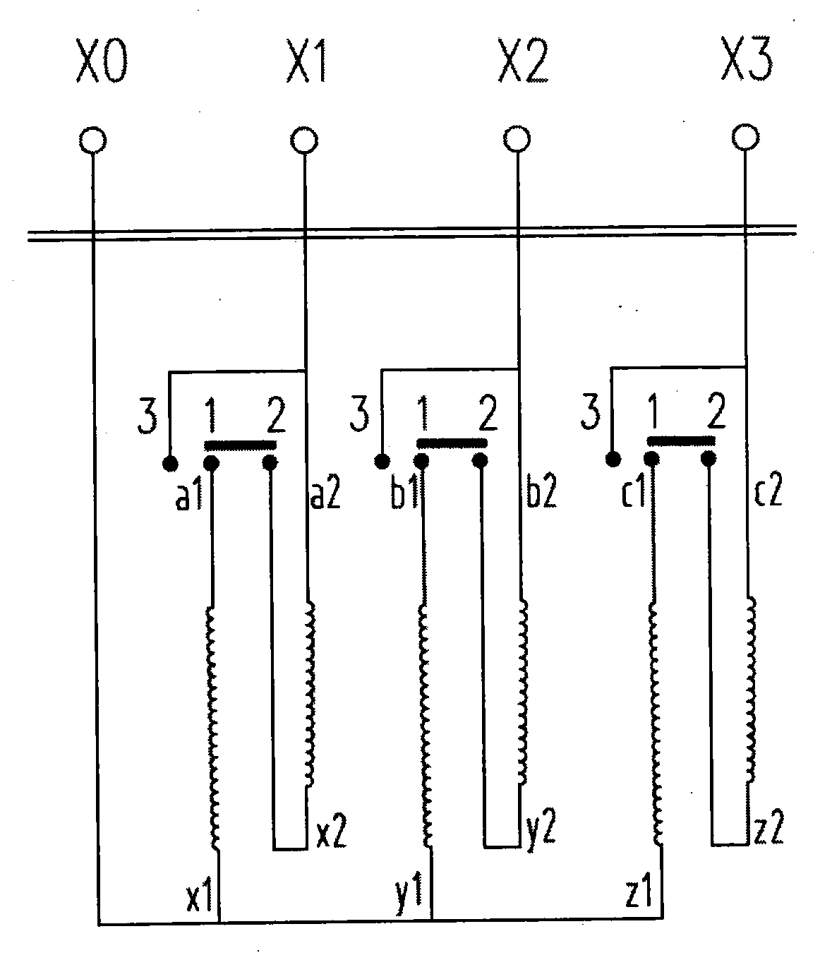
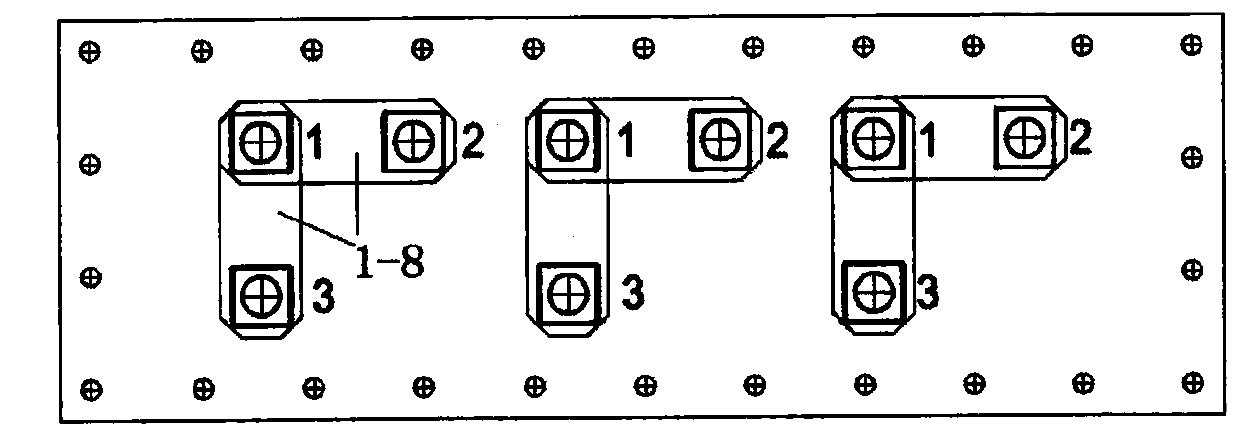
[0021] Such as figure 1 As shown, the device of this embodiment capable of realizing dual-voltage switching on the high-current low-voltage side includes a first contact 1, a second contact 2, a third contact 3 and a shift piece 1-8. The shift Sheets 1-8 connect the first contact 1 with the second contact 2 or connect the first contact 1 with the third contact 3, and the first contact 1 is connected with the first contact draw...


PUM


Abstract

The invention provides a device and method capable of achieving double voltage switching of a high-current and low-voltage side. The device comprises at least one first contact, at least one second contact, at least one third contact and at least one shifting plate, wherein each shifting plate is used for connecting the corresponding first contact and second contact or connecting the corresponding first contact and third contact; each first contact is connected with a first lead which is led out from one end of a first low-voltage coil of a transformer; a second lead which is led out from the other end of the first low-voltage coil of the transformer is connected with a first low-voltage binding post of the transformer; each second contact is connected with a third lead which is led out from one end of a second low-voltage coil of the transformer; and a fourth lead which is led out from the other end of the second low-voltage coil of the transformer is connected with a second low-voltage binding post of the transformer and the corresponding third contact. According to the device and the method provided by the invention, an original change-over switch is concealed on the premise of meeting voltage switching, so that the purchase cost of the switch is greatly reduced and the overall cost of the transformer is also reduced.

Description

technical field [0001] The invention relates to the design field of three-phase oil-immersed transformers, in particular to a device and method for realizing double-voltage switching at a high-current low-voltage side. Background technique [0002] With the increasing export of domestic transformers, for some countries such as Latin America and Africa, due to grid operation problems, the voltage levels are complicated and diverse, and most of the transformers require dual-voltage switching on the low-voltage side. The invention discloses an oil-immersed transformer, which includes a box body and a box cover. The box cover is provided with a low-voltage terminal and a dual-voltage switching device. After the voltage switching device and the low-voltage terminal are connected, the voltage can be adjusted by switching the connection of the voltage switching device on the box cover. [0003] For low-voltage dual-voltage switching transformers, in the transformer design stage, t...

Claims


Application Information

Patent Timeline
Patent Type & Authority Patents(China)
IPC IPC(8): H01F29/02H01F27/40H01F27/14
CPCH01F27/14H01F27/40H01F29/02
Inventor 李锦彪刘亚安黄芝强祝志祥
Owner CHINT ELECTRIC
Why Eureka
Try Eureka