Component mounting apparatus

A technology for mounting machines and components, applied in the direction of electrical components, electrical components, etc., can solve problems such as product quality decline

Active Publication Date: 2017-12-01
FUJI KK
View PDF6 Cites 0 Cited by
  • Summary
  • Abstract
  • Description
  • Claims
  • Application Information

AI Technical Summary

Problems solved by technology

In addition, dust and dust float outside the body, and tape peeling pieces are generated from the tape feeder that supplies components, etc.
Therefore, the dust enters the inside of the body through the opening, thereby deteriorating the quality of the product.

Method used


Image

  • Component mounting apparatus
  • Component mounting apparatus
  • Component mounting apparatus

Examples


Embodiment Construction

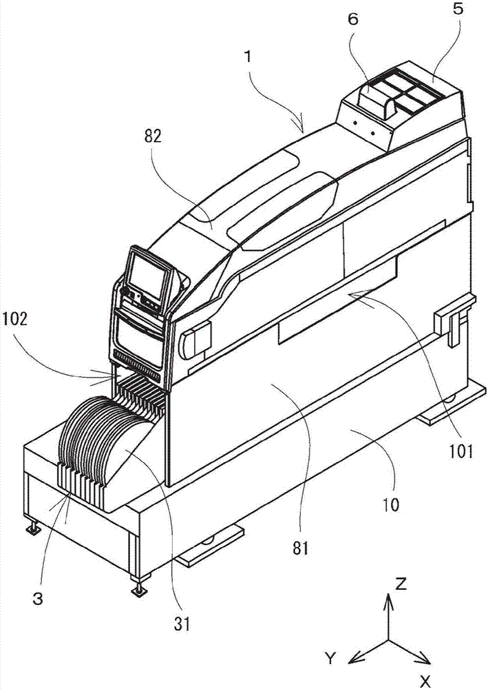
[0020] Next, an embodiment of the component mounting machine of the present invention will be described below with reference to the drawings. In the present embodiment, an electronic component mounting machine for mounting electronic components on a circuit board will be described as an example. figure 1 It is an external appearance perspective view which shows this electronic component mounting machine. The electronic component mounting machine 1 shown here is a structure in which a plurality of mounting machines of the same type are arranged in the width direction to constitute a component mounting line for mounting predetermined electronic components on a circuit board. That is, in the component mounting line, circuit boards are sequentially conveyed into each electronic component mounting machine 1, and predetermined electronic components are mounted in each mounting machine.

[0021] exist figure 1 In the figure, the state where one electronic component mounting machine...


PUM


Abstract

Disclosed is a component mounting apparatus (1) wherein the flowing direction of air supplied to the inside of an apparatus body is adjusted. The component mounting apparatus has: a transfer device (2) that transfers a substrate; a component supplying device (3) having a plurality of components housed therein; a component mounting device (4) that mounts a component on the substrate on the transfer device (2), said component having been taken out from the component supplying device (3); a mounting apparatus main body (81) on which the transfer device (2), the component supplying device (3), and the component mounting device (4) are mounted; a cover member (82) that constitutes the apparatus body by being integrated with the mounting apparatus main body (81), said apparatus body having an opening in a part thereof; an air supply device (5), which is mounted on the cover member (82), and supplies air to the inside of the apparatus body; and a rectifying member (55), which is provided inside of the cover member (82), and guides, to the predetermined direction, the air supplied by the air supplying device (5).

Description

technical field [0001] The present invention relates to a component mounting machine for preventing the intrusion of dust into the inside of a machine body. Background technique [0002] The component mounting machine is entirely covered with a cover member, and mounts components on a board in a work space inside the machine body. That is, in a component mounting machine, components are conveyed to a predetermined supply position by a component supply device, the components are sucked and conveyed by a mounting head provided with suction nozzles, and are mounted on a board carried in by a board conveying conveyor. The component mounting machine is entirely covered by a cover member, but is provided with an opening for supplying components and an opening for carrying in or out of a substrate. In addition, dust and dust float outside the machine body, and a tape peeling piece is generated from a tape feeder or the like that supplies components. Therefore, dust penetrates int...

Claims


Application Information

Patent Timeline
Patent Type & Authority Applications(China)
IPC IPC(8): H05K13/02H05K13/04
CPCH05K13/02H05K13/04
Inventor 岩崎正隆
Owner FUJI KK
Why Eureka
Try Eureka