Clutch device

A technology of clutch device and engagement device, applied in the direction of clutch, friction clutch, mechanical drive clutch, etc., can solve problems such as limiting the degree of freedom of the structure

Active Publication Date: 2017-12-05
SCHAEFFLER TECH AG & CO KG
View PDF6 Cites 2 Cited by
  • Summary
  • Abstract
  • Description
  • Claims
  • Application Information

AI Technical Summary

Problems solved by technology

Due to the increased movement stroke, a larger installation space must be reserved, which limits the degree of freedom of construction

Method used


Image

  • Clutch device
  • Clutch device
  • Clutch device

Examples


Embodiment Construction

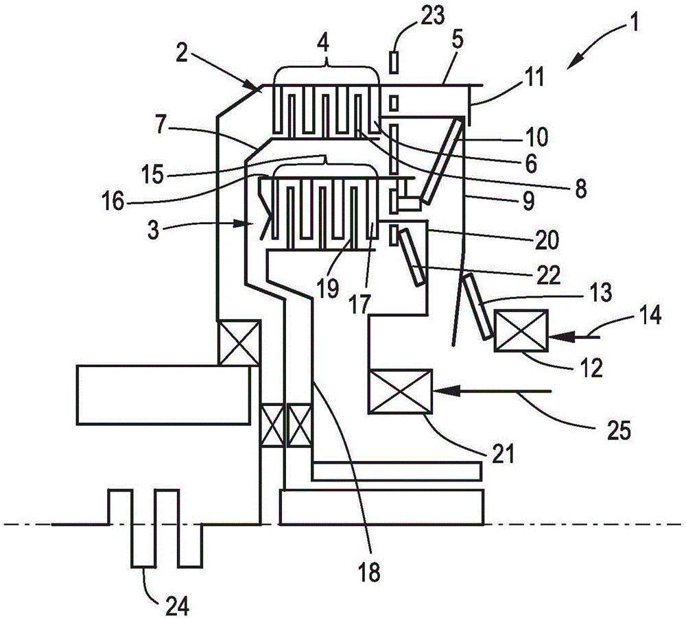
[0025] figure 1 A clutch arrangement 1 is shown, comprising a first partial clutch 2 and a second partial clutch 3 . The first partial clutch 2 comprises a first disk set 4 consisting of an outer disk 6 associated with the first outer disk carrier 5 and an inner disk 8 associated with the first inner disk carrier 7 . Assigned to the first disk pack 4 is a first operating element 9, by means of which an operating force can be introduced into the disk pack 4 so that the first outer disk 6 and the first inner disk 8 can be moved from the open position Move to closed position. Assigned to the first operating element 9 is a first restoring element 10 which generates a restoring force against the operating force so that the operating element 9 returns to the position when the force introduced into the operating element 9 is canceled. figure 1 in the open position shown in . It can be seen that there is also associated with the operating element 9 a first stop device 11 which lim...


PUM


Abstract

A clutch device (29) comprises at least one of an outer disc carrier (5, 16) associated outer plates (6, 17) and an inner disc carrier (7, 18) associated inner plates (8, 19) formed disc set (4, 15), an engagement device comprising a Engaging element (12, 21) and an actuating element (30, 34) for introducing an actuating force into the plate pack (4, 15) and an actuating device for introducing the actuating force into the engaging device and at least one return element (10, 22, 33 , 37), which is designed to build up an actuating force counteracting the restoring force, wherein the engagement element (12, 21) and the actuating element (30, 34) are coupled or coupled such that the actuating element (30, 34) during a movement of Engaging element (12, 21) between a basic position and an idle stroke position or in a closed position v remains and that the actuating element (30, 34) during a movement of the engagement element (12, 21) beyond the idle stroke position of the open position into the closed position or from the closed position to the open position is movable.

Description

technical field [0001] The invention relates to a clutch device, comprising at least one friction disc set, an engagement device, an operating device for introducing an operating force to the engagement device and at least one return element coupled with the engagement device, the friction disc set being composed of a matching The outer discs belonging to the outer disc carrier and the inner discs associated with the inner disc carrier consist of an engaging device comprising an engaging element and an operating element for introducing an operating force into the disc set, the return The element is designed to form a restoring force counteracting the actuating force. Background technique [0002] In such clutch devices known from the prior art, an actuating force is generated by the actuating device, which is introduced into a coupling element coupled to the actuating element. The actuating element is thus moved towards the disk pack, whereby the inner and outer disks assig...

Claims


Application Information

Patent Timeline
Patent Type & Authority Applications(China)
IPC IPC(8): F16D13/54F16D13/58F16D13/70F16D21/00
CPCF16D13/54F16D13/58F16D13/70F16D21/00F16D21/06F16D2021/0676
Inventor O·诺尔F·比尔曼M·奥特A·鲍姆加特纳
Owner SCHAEFFLER TECH AG & CO KG
Why Eureka
Try Eureka