
Work device

一种工作器械、工具的技术,应用在仪器、切割工具、机械设备等方向,能够解决操作者疲劳等问题

Inactive Publication Date: 2014-06-18
ANDREAS STIHL AG & CO KG
View PDF9 Cites 1 Cited by
  • Summary
  • Abstract
  • Description
  • Claims
  • Application Information

AI Technical Summary

Problems solved by technology

Work above the rotational speed determined by the intermediate stop is thus tiring for the operator

Method used


Image

  • Work device
  • Work device
  • Work device

Examples


Embodiment Construction

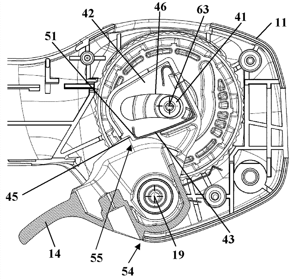
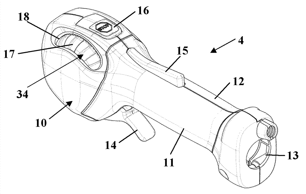
[0036] figure 1 A hand-held power tool, a field trimmer 1 , is shown as an example for a power tool. However, the design of the intermediate stop described below can also be used advantageously in other work implements, in particular in other hand-held work implements, especially in sprayers (Sprühgeröt), blowers (Blasgeröt), hedge trimmers ( Heckenschere), olive harvesters (Olivenernter) or similar objects. For blowers and sprinklers, the means are fan impellers (Geblöserad) which deliver the working air flow. For harvesting devices such as olive harvesters or the like, the tools are formed by moving fingers, hooks or the like that act into the tree or shrub.

[0037] The trimmer 1 has a motor housing 2 in which the figure 1 Drive motor not shown. The motor housing 2 is connected via a guide tube 3 to a mowing head 6 , from which a cutting wire 7 protrudes. The cutting head 6 is driven in rotation. The flight circumference of the cutting wire 7 is partially covered by a...


PUM


Abstract

EA work apparatus has a drive motor for driving a work tool and has a control unit for the drive motor. The operating device includes an actuating element actuated by a user. The actuating element is mounted in a movable manner in a housing and can be adjusted in an actuating direction between a zero position and a maximum position. An intermediate stop acts between the zero position and the maximum position. The position of the intermediate stop is settable via a setting element. After the intermediate stop has been reached, the actuating element can be actuated further as far as the maximum position. The operating force (F) for further actuating the actuating element increases when the intermediate stop is reached. Provision is made for the operating force (F) to drop again upon further actuation of the actuating element after the intermediate stop has been overcome.

Description

technical field [0001] The invention relates to a power tool (Arbeitsgeröt) with a drive motor and an operating device according to the type specified in the preamble of claim 1 . Background technique [0002] In work implements such as trimmers or the like, it may be desirable for some applications to operate the work implement at a constant rotational speed that is reduced relative to the maximum rotational speed in order to achieve the desired cutting result. From EP 1 223 318 B1 and US 5,765,445 A, an adjustable intermediate stop (Zwischenanschlag) for the accelerator lever (Gashebel) is known, with which the operator can easily hold the accelerator lever in a partially actuated in the location. The intermediate stop includes a spring. After reaching the intermediate stop, the accelerator lever can be further actuated against the force of the spring. For this, high operating forces must be applied. Likewise, in order to hold the accelerator lever in the full speed po...

Claims


Application Information

Patent Timeline
Patent Type & Authority Applications(China)
IPC IPC(8): A01D34/90
CPCF02D11/02G05G5/04F02B63/02A01D2034/907
Inventor A.格策尔J.赫贝莱茵
Owner ANDREAS STIHL AG & CO KG
Learn More