Keying switch

A key and switch technology, applied in the field of key switches, can solve the problems of complex reset mechanism and poor workmanship of piano key switches, and achieve the effects of small operating force, safe and reliable use, and sensitive action

Inactive Publication Date: 2006-03-01
TCL INT ELECTRICAL HUIZHOU
View PDF1 Cites 12 Cited by
  • Summary
  • Abstract
  • Description
  • Claims
  • Application Information

AI Technical Summary

Problems solved by technology

This invention discloses a switch mechanism part that makes the switch alternately turn over in the invention patent publication specification. The switch mechanism part realizes the alternate turnover and reset of the switch through the cooperation of the sliding cam and the recovery spring. However, the reset mechanism of the keyboard switch is complicated and poor in manufacturability.

Method used


Image

  • Keying switch
  • Keying switch
  • Keying switch

Examples


Embodiment Construction
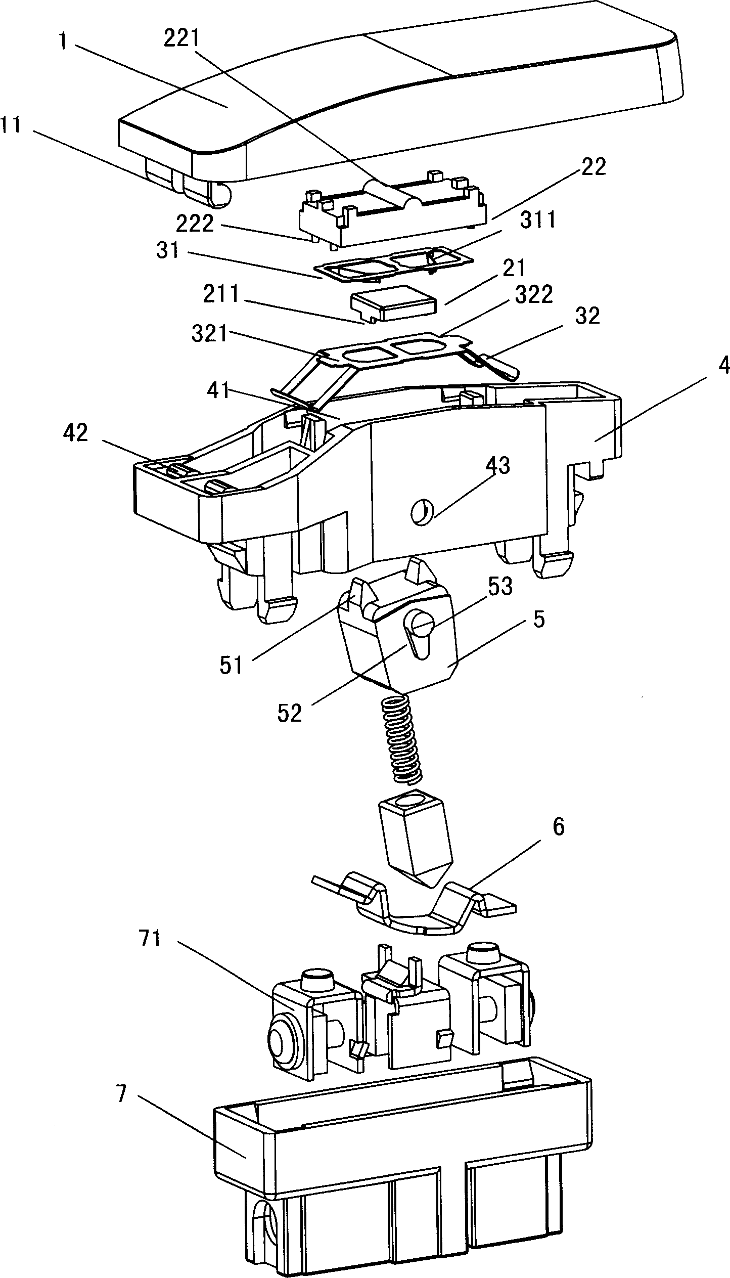
[0014] The basic idea of ​​the present invention is to connect the button cover and the base up and down through the housing frame, and install a reset mechanism composed of a rocker, a reset spring, etc. , to realize that after pressing the key cover, the switch contacts can be flipped alternately and the original position can be restored after the pressing operation of the key cover is completed. The present invention will be further described in detail below through the embodiments in conjunction with the accompanying drawings.

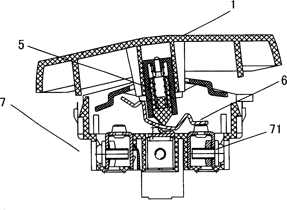
[0015] figure 1 The basic assembly structure of the commercially available push-button switch is described, and since it has been explained in the background technology section, it will not be repeated here.

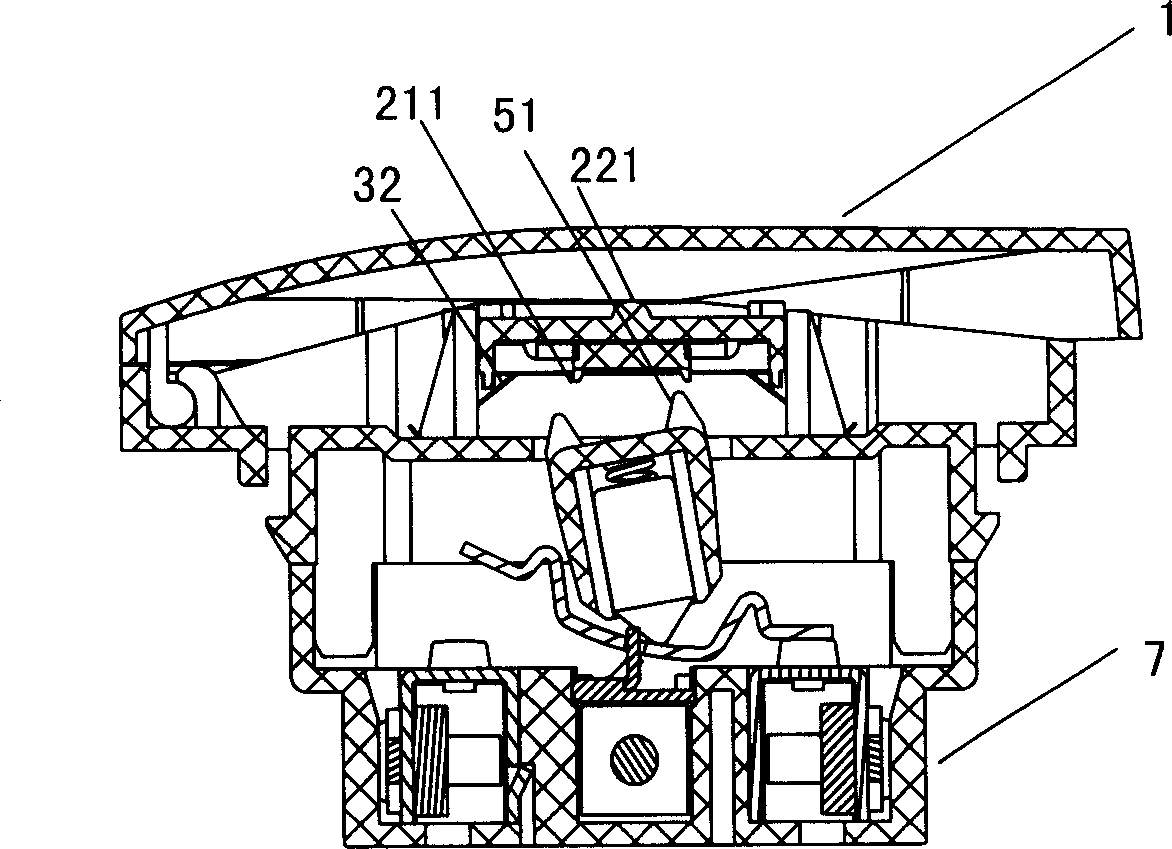
[0016] Figure 2-9 Provides a detailed description of the basic structure of Embodiment 1. First, the parts and their serial numbers are described below: button cover 1, L-shaped buckle 11, cross bar 12, slider one 21, wedge-shaped protrus...


PUM


Abstract

A switch of key type consists of key cover, base, containing frame and reset mechanism. It is featured as setting reset mechanism in containing frame between key cover and base; pressing down key cover to let reset mechanism coordinate slide block , link rod ,reset spring , etc for turning over switch contact alternatively; and restoring switch to be initial position when key cover is released.

Description

technical field [0001] The invention relates to a key switch, in particular to a civil key switch with an automatic reset mechanism. Background technique [0002] Push-button switch is the most common and common electrical component used to control the on-off of electrical equipment. The ordinary push-button switch is a double-position type. Keeping it in different positions, it is common that the height of the same end is different, which makes the overall appearance of the switch uneven, with a low overall sense and poor fluency. figure 1 Shown is a common manual push-type switch, which includes a key cover 1 and a base 7, a terminal 71 is provided in the base, a rocker 5 is provided between the base 7 and the key cover 1, and a spring is provided in the rocker , the position of the rocker is in the slideway inside the button cover, forming a T-shaped structure with the button. In the initial state, the rocker is located on one side of the seesaw 6, and when the key cove...

Claims


Application Information

Patent Timeline
Patent Type & Authority Applications(China)
IPC IPC(8): H01H13/56H01H13/60H01H19/36H01H21/36
Inventor 田赡民安东明何均匀
Owner TCL INT ELECTRICAL HUIZHOU
Why Eureka
Try Eureka