Backlight module and display panel

A backlight module and backplane technology, which is applied in optics, nonlinear optics, instruments, etc., can solve the problems affecting the light quality of the backlight module and inconsistent brightness, so as to improve the quality of light emitted, avoid chromatic aberration, and improve brightness Effect

Active Publication Date: 2020-05-29
SHENZHEN CHINA STAR OPTOELECTRONICS SEMICON DISPLAY TECH CO LTD
View PDF6 Cites 28 Cited by
  • Summary
  • Abstract
  • Description
  • Claims
  • Application Information

AI Technical Summary

Problems solved by technology

[0006] The purpose of the present invention is to provide a backlight module and a display panel to solve the problems in the prior art that dark lines are generated at the splicing position of mini LED lamp panels, and the color tone of the splicing position is inconsistent with the brightness of the normal light-emitting area, which affects the light quality of the backlight module. technical problem

Method used


Image

  • Backlight module and display panel
  • Backlight module and display panel
  • Backlight module and display panel

Examples


Embodiment 1

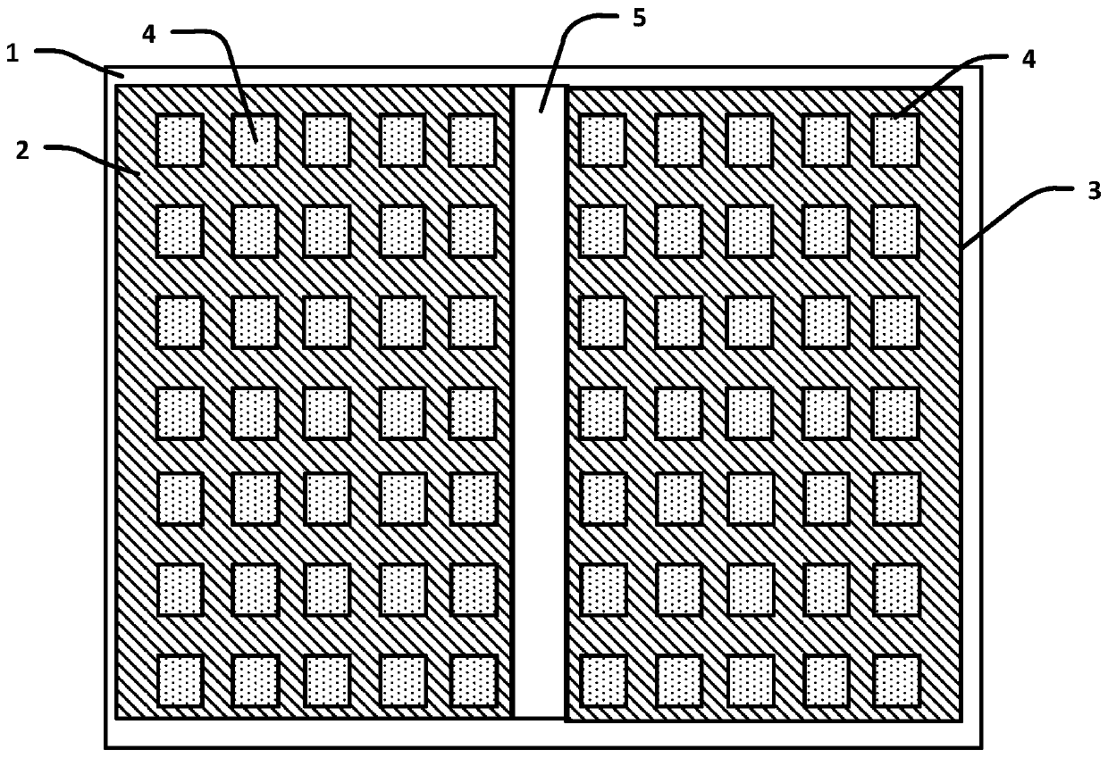
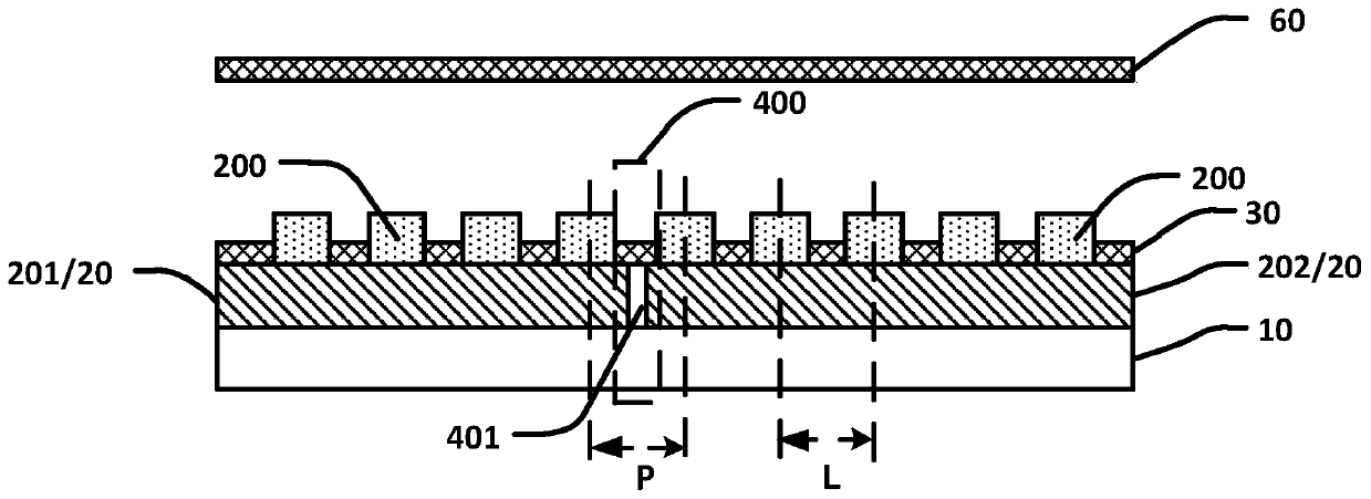
[0046] Such as image 3 As shown, this embodiment provides a backlight module, including a backplane 10 , a lamp panel 20 and a reflective layer 30 .

[0047] A plurality of lamp panels 20 are spliced ​​and arranged on the upper surface of the back panel 10 in an array. Mini-LEDs 200 are arranged in an array on the upper surface of each lamp board 20 .

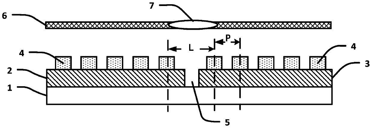
[0048] The splicing area 40 is located between the adjacent first lamp board 201 and the second lamp board 202 , the splicing area 40 has a splicing seam 401 , and the filling light material is filled in the splicing seam 401 . Wherein, the supplementary light material includes white polycarbonate (Polycarbonate, PC) and / or white titanium dioxide (TiO2). The distance between the nearest Mini-LEDs 200 between the adjacent first lamp board 201 and the second lamp board 202 is L (equivalent to the width of the splicing area 40 ), the Mini-LEDs 200 in the first lamp board 201 and the second lamp board 202 The pitch (Pitch) is P. ...

Embodiment 2

[0054] This embodiment provides a backlight module and a display panel, including most of the technical solutions in Embodiment 1, the difference being that L>P, and the backlight module further includes a reflective sheet.

[0055] Such as Figure 4-8 As shown, the two adjacent lamp panels 20 are the first lamp panel 201 and the second lamp panel 202 respectively.

[0056] Mini-LEDs 200 are arranged in an array on the upper surface of each lamp board 20, including N columns and M rows, wherein N and M are both positive integers. Wherein, the Mini-LEDs 200 in the Nth column and / or the 1st column are adjacent to one of the splicing regions 40 .

[0057] Such as Figure 4-5 As shown, the reflection sheet 50 can be disposed between the Nth column and the N−1th column of the first lamp panel 201 , or between the first column and the second column of the second lamp panel 202 .

[0058] Such as Figure 6-7 As shown, the reflection sheet 50 may also be disposed between the Nth c...

Embodiment 3

[0067] This embodiment provides a backlight module and a display panel, including most of the technical solutions of Embodiment 2. The difference is that the lamp panels in Embodiment 2 are spliced ​​vertically, while the lamp panels in this embodiment are spliced ​​horizontally.

[0068] Such as Figure 9-12 As shown, the adjacent two lamp panels are the third lamp panel 203 and the fourth lamp panel 204 respectively. Mini-LED200 is arranged in an array on the upper surface of each light board, including N columns and M rows, where N and M are both positive integers; the Mini-LEDs in the M row and / or the 1st row are adjacent to it A stitching area.

[0069] Such as Figure 9-10 As shown, the reflection sheet 50 is disposed between the Mth row and the M-1th row of the third lamp panel 203 , or between the first row and the second row of the fourth lamp panel 204 .

[0070] Such as Figure 11-12 As shown, the reflection sheet 50 is disposed between the Mth row and the M-1th...


PUM

PropertyMeasurementUnit
angleaaaaaaaaaa

Abstract

The invention provides a backlight module and a display panel. The backlight module comprises a back plate, lamp panels and a reflecting layer, wherein a plurality of lamp panels are arranged on an upper surface of the back plate in an array splicing manner, splicing areas are arranged between every two adjacent lamp panels, each splicing area is provided with a splicing seam, light supplementingmaterials are arranged in the splicing seams, and the reflecting layer is arranged on upper surfaces of the lamp panels and the splicing areas. The backlight module is advantaged in that the splicingseam is filled with the light supplementing materials and an emission sheet is arranged between a Mini-LED of a first column/row and a Mini-LED of a second column/row, the Mini-LED of the first column/row is closest to the Mini-LED of the second column/row, the Mini-LED is arranged in the splicing area so that light emitted by the Mini-LED is reflected to a reflector plate, the reflector plate reflects the light to the position of the splicing areas, the light-emitting hue of the splicing position is consistent with that of a normal area, brightness of the splicing areas is improved, chromaticaberration of the splicing areas is avoided, and the quality of light emitted by a backlight module is improved.

Description

technical field [0001] The present application relates to the field of display technology, in particular to a backlight module and a display panel. Background technique [0002] The mini-light-emitting diode (Mini-LED) is small in size and is used to realize ultra-thin multi-partition, which is the current development technology direction of the industry. [0003] At present, the industry uses Mini-LED as a backlight to match with a Liquid Crystal Display (LCD) panel to achieve ultra-thin, high-brightness, and multiple partitions. As the number of partitions increases, so does the need for partitions. Therefore, an active matrix driving (Active Matrix, AM) method is proposed, and the active matrix driving is realized by using a TFT structure formed on a glass substrate in combination with a scanning method. When using AM TFT design structure, because the external circuit is implemented by COF bonding, there must be a larger distance between the LEDs on the source side than...

Claims


Application Information

Patent Timeline
Patent Type & Authority Applications(China)
IPC IPC(8): G02F1/13357
CPCG02F1/133603G02F1/133605G02F1/133611
Inventor 张鑫丘永元付琳琳程希
Owner SHENZHEN CHINA STAR OPTOELECTRONICS SEMICON DISPLAY TECH CO LTD
Why Eureka
Try Eureka