Space saving miniature connector for electric devices

a technology for electric devices and connectors, applied in the direction of coupling device connections, coupling contact members, engagement/disengagement of coupling parts, etc., can solve the problems of difficult to guide a connecting object, difficult to achieve a reduced overall height, and difficult to arrange contacts above and below. achieve the effect of reducing the overall heigh

Inactive Publication Date: 2009-11-24
DDK LTD
View PDF16 Cites 13 Cited by
  • Summary
  • Abstract
  • Description
  • Claims
  • Application Information

AI Technical Summary

Benefits of technology

[0039]As can be seen from the above description, the connectors according to the invention can bring about the following significant effects.
[0040](1) according to the first and third invention, a reduced overall height to an extent of the order of 1.0 mm, a miniaturization of the connector and narrower pitches are possible, and a space-saving for a substrate (particularly, to 3.0 mm in length in the inserting direction) can be obtained. As compared with the front locking type and rear locking type connectors of the prior art, according to the invention a locking length more than 2 mm can be ensured, and a stable connection can be obtained with simple operation and slight operating force because the part to be actuated by a finger becomes larger. In addition, according to the first invention, even if a connecting object is accidentally subjected to external forces, failed connection can be prevented as compared with the prior art (stable connection and holding force are more improved in comparison with the prior art as is clear by referring to Tables 1 and 2).
[0041](2) According to the second and fourth inventions, more space-saving for a substrate in the inserting direction can be achieved in comparison with the first and third inventions. As compared with the front locking type and rear locking type connectors of the prior art, a locking length can be assured, and a stable connection can be obtained with a simple operation and slight operating force because the part to be actuated by a finger becomes larger.
[0042](3) According to the invention, said holding means comprises a projection 40 provided on said pressure receiving portion 34 of said first piece 28 of at least every other contact 14 or to extend toward said connection portion 36, and a protrusion 42 provided in the proximity of tip of the connection portion 36 of said second piece 30 of the at least every other contact 14 to extend toward said pressure receiving portion 34. Therefore, said pivoting member 16 can be safely rotated, and as the pivoting member 16 is rotated toward the fitting opening side, the area occupied by the substrate becomes smaller (length in the inserting direction becomes 3.0 mm).
[0043](4) According to the invention, said holding means comprises a raised portion 44 provided between the connection portion 36 of said second piece 30 and said jointing portion 38 of at least every other contact 14 to extend toward said pressure receiving portion 34. Accordingly, said pivoting member 16 can be safely rotated, and as the pivoting member 16 is rotated toward the fitting opening side, the area occupied by the substrate becomes smaller (length in the inserting direction becomes 3.0 mm).
[0044](5) According to the invention, contacts 14 each provided with said projection 40 and said protrusion 42, and contact 14 each provided with said raised portions 44 are alternately arranged so that said projections, said protrusions and said raised portions are alternately staggered. Therefore, said pivoting member 16 can be easily inserted and can be safely rotated, and as the pivoting member 16 is rotated toward the fitting opening side, the area occupied by the substrate becomes smaller (length in the inserting direction becomes 3.0 mm) and a narrow pitch of the connector can be achieved.

Problems solved by technology

With the front locking type connector disclosed in the Patent Literature 2, since the pivoting member is rotated on the side of the fitting opening, it is impossible to arrange the contacts above and below, and makes it difficult to achieve a reduced overall height (height of the order of 1 mm).
With this type of connector, moreover, it is difficult to guide a connecting object because the actuator is under the opened condition (there is no wall on the ceiling side) when the connecting object is inserted into the connector.
With the rear locking type connectors disclosed in the Patent Literatures 1 and 3, on the other hand, since the pivoting member such as the actuator is rotated on the opposite side of the fitting opening, when the connecting object such as the flexible printed circuit board is connected to the connector, part of the pivoting member extends from one end face of the connector to form a dead space for a substrate, thereby making impossible to save the space of the substrate in the inserting direction of the connecting object.

Method used


Image

  • Space saving miniature connector for electric devices
  • Space saving miniature connector for electric devices
  • Space saving miniature connector for electric devices

Examples


Embodiment Construction

[0105]One embodiment of the connector according to the invention will be explained with reference to FIGS. 1 to 5.

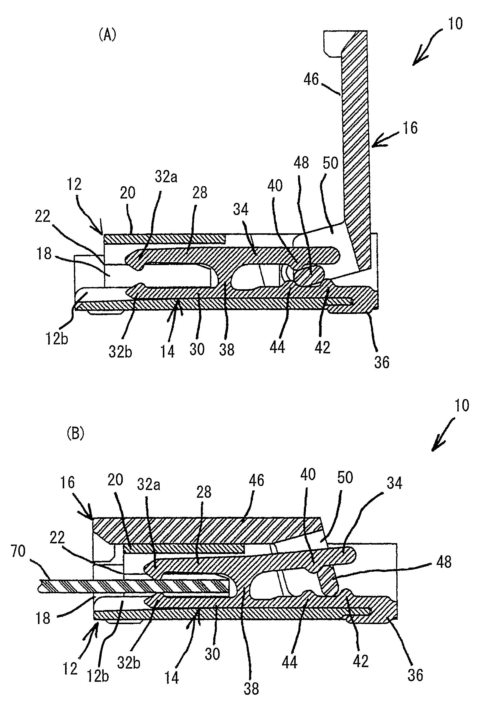
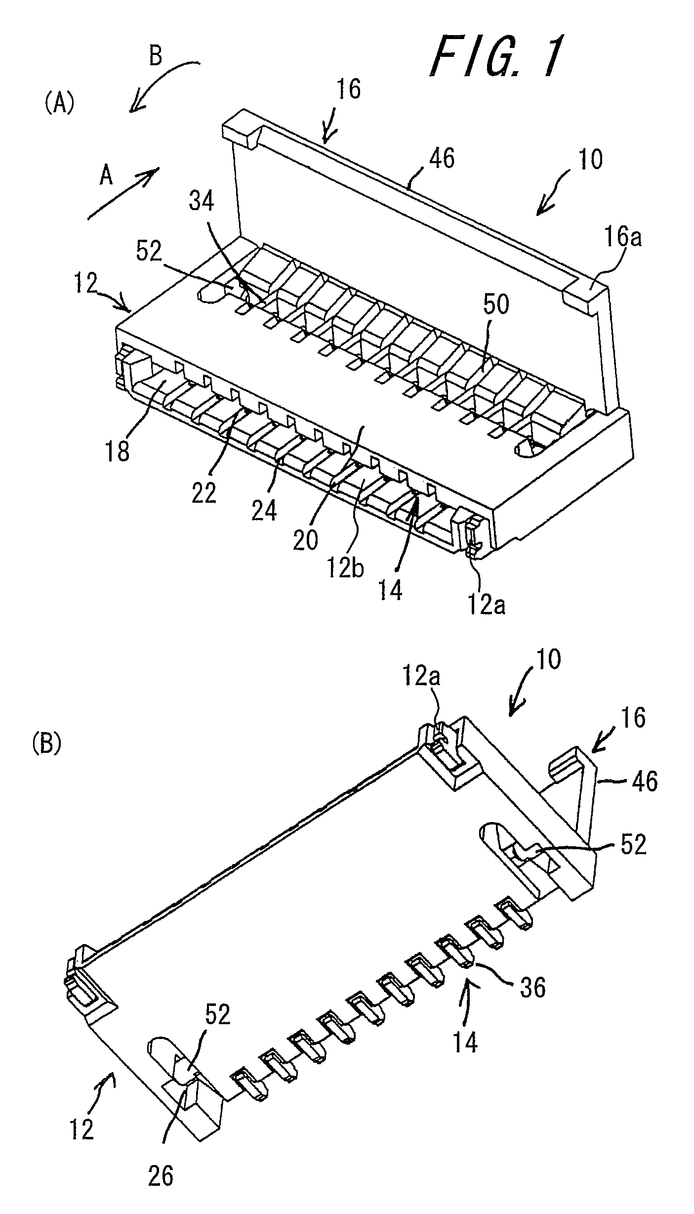
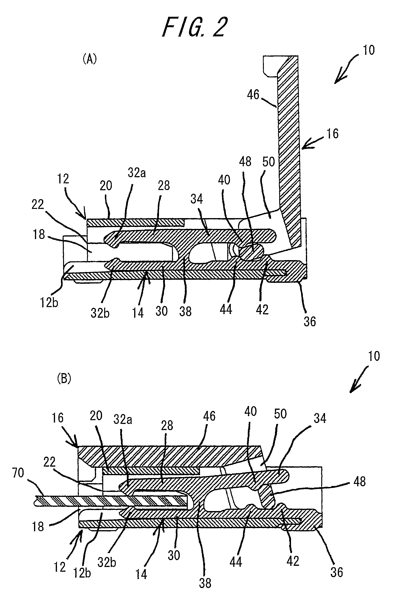
[0106]FIG. 1(A) is a perspective view of the connector according to the invention with its pivoting member opened, viewed from its fitting opening side, and FIG. 1(B) is a perspective view of the connector with its pivoting member opened, viewed from the connection portion side. FIG. 2(A) is a sectional view of the connector according to the invention with the pivoting member opened, taken along one contact, while FIG. 2(B) is a sectional view of the connector with a flexible printed circuit board inserted and the pivoting member closed, taken along the contact. FIG. 3(A) is a perspective view illustrating the contacts used in FIGS. 1 and 2. FIG. 4 is a perspective view of the pivoting member. FIG. 5(A) to (F) illustrates explanatory views for explaining movements of pushing portion and axis of rotation when the pivoting member is pivotally moved from its opened position...


PUM


Abstract

The invention has an object to provide a connector 10 which achieves a reduced overall height of the order of 1.0 mm and space-saving substrate (in the inserting direction of a circuit board) and which obtains stable connection with a slight operating force and does not cause any defective connection even if a connecting object is accidentally subjected to an external force. The object is accomplished by a connector comprising substantially H-shaped contacts 14 each including a first piece 28 having a contact portion 32 and a pressure receiving portion 34, a second piece 30 having a contact portion 32 and a connection portion 36, and a jointing portion 38 connecting these first and second pieces, and further including holding device permitting pushing portions 48 of a pivoting member 16 to pivotally move between the pressure receiving portions 34 and the connection portions 36, a housing 12 having a ceiling portion 20 formed at least at both ends with protection walls 22 for preventing the ceiling portion 20 from being upwardly deformed when the connecting object is accidentally forced upwardly, and the pivoting member 16 including the pushing portions 48, anchoring holes 50 independently from one another and an actuating portion 46 which is pivotally moved toward a fitting opening 18 of the housing 12 to bring the contact portions 32 of the contacts 14 into contact with the connecting object.

Description

TECHNICAL FIELD[0001]This invention relates to a connector for use in electric and electronic appliances such as mobile appliances and the like, and more particularly to a connector which achieves stable electrical connection with a connecting object such as a flexible printed circuit board or flexible flat cable and minimization of area occupied by a substrate.BACKGROUND ART[0002]Connectors for use in mobile phones, CCD cameras (charge coupled device cameras) and the like are very thin in overall height and have extremely narrow pitches (so-called lighter and more compact). Such connectors each mainly comprise a housing, contacts and slider to embrace a flexible printed circuit board or flexible flat cable between the housing and the slider. Various methods may be considered for holding a flexible printed circuit board or flat cable by the housing and the slider. There are many constructions that after a flexible printed circuit board or flat cable has been inserted into a housing,...

Claims


Application Information

Patent Timeline
Patent Type & Authority Patents(United States)
IPC IPC(8): H01R13/15H01R13/62H01R12/72H01R12/77H01R12/79H01R12/85H01R24/00H01R24/60
CPCH01R12/73H01R12/88H01R12/79H01R12/77
Inventor SUZUKI, MASAYUKINAKANO, YUUKI
Owner DDK LTD
Why Eureka
Try Eureka