Automatic magnetic buckle and automatic buckling method

A buckle and automatic technology, applied in the direction of mechanical equipment, fixing devices, etc., can solve the problems of unstable fixing, inaccurate connection position, poor practicability, etc., and achieve the effect of saving operation steps and time and improving practicability

Active Publication Date: 2017-12-08
东莞明冠织带制品有限公司
View PDF7 Cites 5 Cited by
  • Summary
  • Abstract
  • Description
  • Claims
  • Application Information

AI Technical Summary

Problems solved by technology

[0002]Current buckles are magnetically connected by adding block-shaped magnetic parts. The fixation is unstable; and the hook of the existing buckle is an integral structure, which requires both hands to operate when fastening and separating, which is inconvenient to operate and poor in practicability

Method used


Image

  • Automatic magnetic buckle and automatic buckling method
  • Automatic magnetic buckle and automatic buckling method
  • Automatic magnetic buckle and automatic buckling method

Examples


Embodiment 1

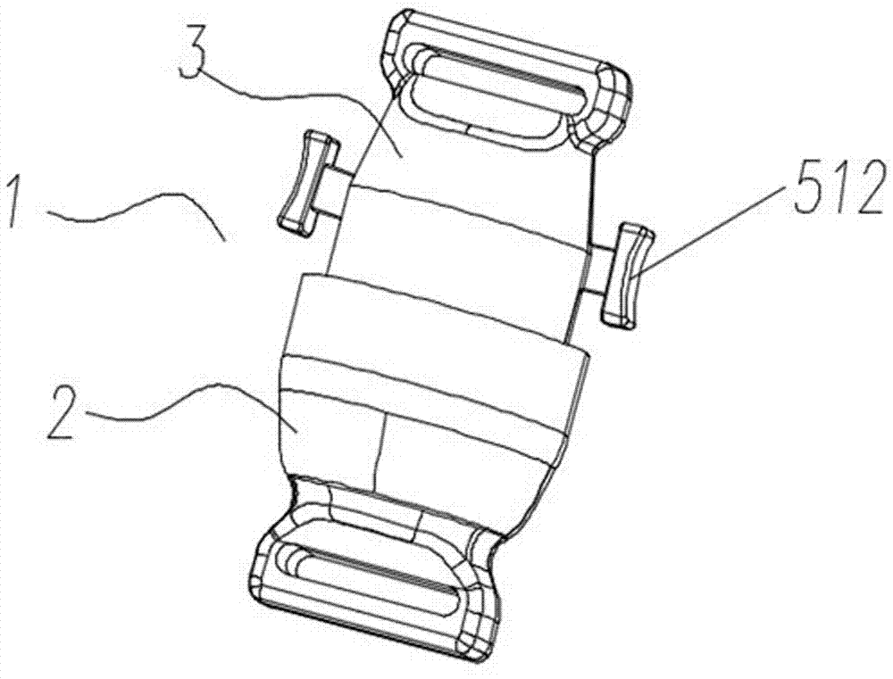
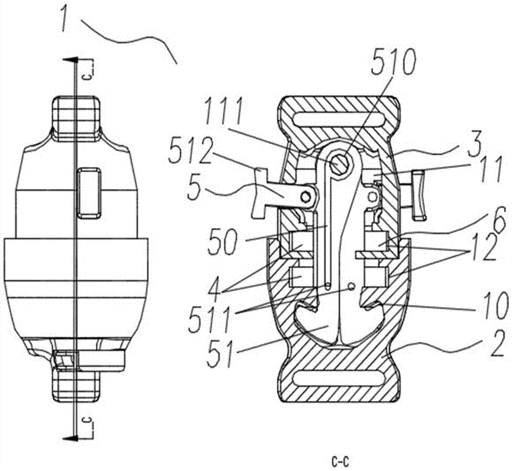
[0040] Embodiment 1, see attached Figure 1~6 , an automatic magnetic buckle including a buckle body 1, the buckle body 1 is provided with a buckle seat 2, a buckle head 3, a magnetic attraction component 4 and a buckle component 5; the buckle seat 2 is provided with an annular fastening groove 6. The buckle component 5 is mated and fastened with the ring-shaped fastening groove 6 , the magnetic attraction component 4 is respectively set in the buckle seat 2 and the buckle head 3 , and the buckle component 5 is set in the buckle head 3 .

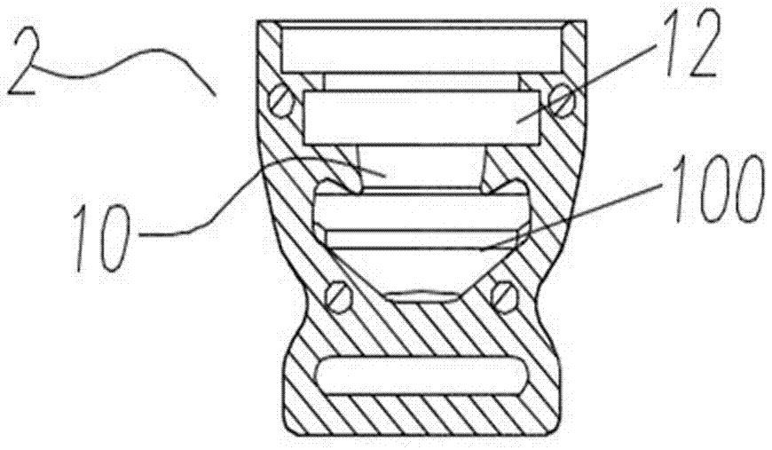
[0041] The buckle body 1 is provided with a cavity one 10 and a cavity two 11, the cavity one 10 is set in the buckle seat 2, the cavity two 11 is set in the buckle head 3, and the buckle assembly 5 is arranged in the cavity two 11 of the buckle head 3; the cavity one 10 and the cavity two 11 are provided with a magnetic attraction component placement cavity 12, and the cavity one 10 is also provided with a hook cavity 100, and the cavity tw...

Embodiment 2

[0045] Embodiment 2, see attached Figure 1~5 and Figure 8 , an automatic magnetic buckle including a buckle body 1, the buckle body 1 is provided with a buckle seat 2, a buckle head 3, a magnetic attraction component 4 and a buckle component 5; the buckle seat 2 is provided with an annular fastening groove 6. The buckle component 5 is mated and fastened with the ring-shaped fastening groove 6 , the magnetic attraction component 4 is respectively set in the buckle seat 2 and the buckle head 3 , and the buckle component 5 is set in the buckle head 3 .

[0046]The buckle body 1 is provided with a cavity one 10 and a cavity two 11, the cavity one 10 is set in the buckle seat 2, the cavity two 11 is set in the buckle head 3, and the buckle assembly 5 is arranged in the cavity two 11 of the buckle head 3; the cavity one 10 and the cavity two 11 are provided with a magnetic attraction component placement cavity 12, and the cavity one 10 is also provided with a hook cavity 100, and...

Embodiment 3

[0050] Embodiment 3, see attached Figure 1~5 and Figure 7 , an automatic magnetic buckle including a buckle body 1, the buckle body 1 is provided with a buckle seat 2, a buckle head 3, a magnetic attraction component 4 and a buckle component 5; the buckle seat 2 is provided with an annular fastening groove 6. The buckle component 5 is mated and fastened with the ring-shaped fastening groove 6 , the magnetic attraction component 4 is respectively set in the buckle seat 2 and the buckle head 3 , and the buckle component 5 is set in the buckle head 3 .

[0051] The buckle body 1 is provided with a cavity one 10 and a cavity two 11, the cavity one 10 is set in the buckle seat 2, the cavity two 11 is set in the buckle head 3, and the buckle assembly 5 is arranged in the cavity two 11 of the buckle head 3; the cavity one 10 and the cavity two 11 are provided with a magnetic attraction component placement cavity 12, and the cavity one 10 is also provided with a hook cavity 100, an...


PUM


Abstract

The invention discloses an automatic magnetic buckle, which comprises a buckle main body; a buckle base, a buckle head, magnetic suction components and a buckle component are arranged at the buckle main body; the buckle base is provided with an annular buckling groove, and the buckle component is buckled and connected with the annular buckling groove; magnetic suction components are arranged in the buckle base and the buckle head, and the buckle component is arranged in the buckle head. The invention further discloses an automatic buckling method. The invention relates to the technical field of the magnetic suction components; through mutual absorption of the magnetic suction components, the buckle base and the buckle head can be connected automatically and rapidly; besides, the buckling time is saved through the rapid buckling of the buckling component; the buckling at different angles can be realized through the magnetic suction components of the annular structure, and the annular magnetic suction components have oblique faces and matched with the oblique faces of arrow-shaped structure hanging hooks, thus the buckle head is automatically slipped to buckle under the effect of the magnetic force, and the buckling is convenient; the hanging hook opening and closing are controlled through a reset spring, and it is convenient to control by users through a tripping structure.

Description

technical field [0001] The invention relates to the technical field of buckle structures, in particular to an automatic magnetic buckle and an automatic buckle method. Background technique [0002] The current buckle is magnetically connected by adding a block magnetic suction part, and the connection is limited by the angle, which may easily cause inaccurate connection position and cause unstable fixation; and the hook of the existing buckle is integral structure, when fastening and separating, both hands are required to operate, which is inconvenient to operate and poor in practicability. Contents of the invention [0003] The present invention aims at present technical deficiencies and provides an automatic magnetic buckle. [0004] The invention also provides an automatic fastening method. [0005] The technical scheme that the present invention adopts for realizing the above object is: [0006] An automatic magnetic buckle, which includes a buckle body, the buckle ...

Claims


Application Information

Patent Timeline
Patent Type & Authority Applications(China)
IPC IPC(8): F16B1/00
CPCF16B1/00
Inventor 屈芳盟
Owner 东莞明冠织带制品有限公司
Why Eureka
Try Eureka