Buckling device for safety belt

a safety belt and buckle technology, applied in the direction of garment fasteners, fastenings, press-button fasteners, etc., can solve the problems of heavy weight and inconvenient operation, and achieve the effect of easy buckle buckle buckling

Inactive Publication Date: 2011-10-25
TAIWAN RACING PRODS
View PDF5 Cites 6 Cited by
  • Summary
  • Abstract
  • Description
  • Claims
  • Application Information

AI Technical Summary

Benefits of technology

[0009]The primary object of the present invention is to provide a buckling device for safety belts that in buckling operation, the engagement member of the locking unit can be at any position without being rotated to a certain angle to directly engage the narrower segment of the fastening member with the buckle. The engagement member pushes the mounting member of the locking unit, so that the knob of the mounting member is retained in the retaining pore of the fastening member by using a torsion spring, making buckling the buckle easy.
[0010]A further object of the present invention is to provide a buckling device for safety belts that in buckling operation, the mounting member of the locking unit retains the knob in the retaining pore of the fastening member by a torsion spring, and the two ends of the fixing piece of the locking unit engage the recesses of the second side plates of the locking unit to achieve a two-section buckling operation, providing a preferred safety.
[0011]Another object of the present invention is to provide a buckling device for safety belts that the holder of the buckle is formed of a metal plate, lowering its weight.

Problems solved by technology

1. In buckling operation, the engagement member of the buckling device has to be rotated to a certain angle to insert the fastening member into the buckle, making operating inconvenient.
2. The conventional buckling devices are buckled in a one-section operating manner to disengage the engagement member easily, causing unsafety in car crashes.
3. The holder of the conventional buckles is forged, resulting in a heavy weight.

Method used


Image

  • Buckling device for safety belt
  • Buckling device for safety belt
  • Buckling device for safety belt

Examples


Embodiment Construction

[0023]The present invention will be clearer from the following description when viewed together with the accompanying drawings, which show, for purpose of illustration only, the preferred embodiment in accordance with the present invention.

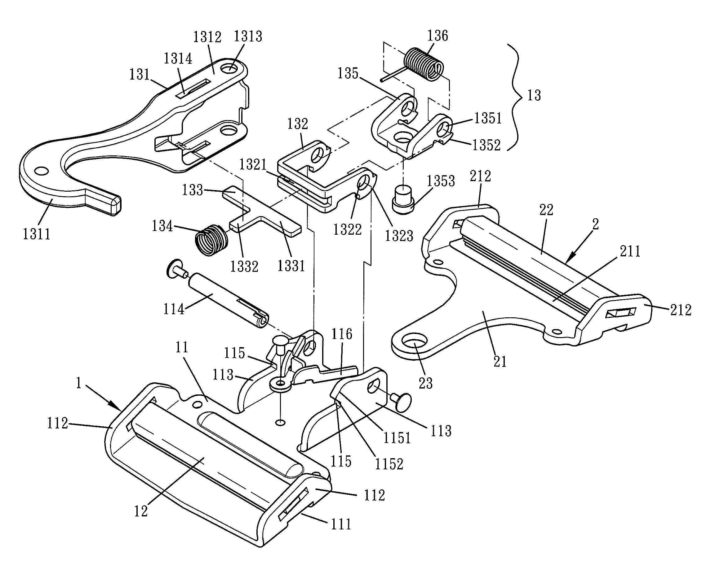
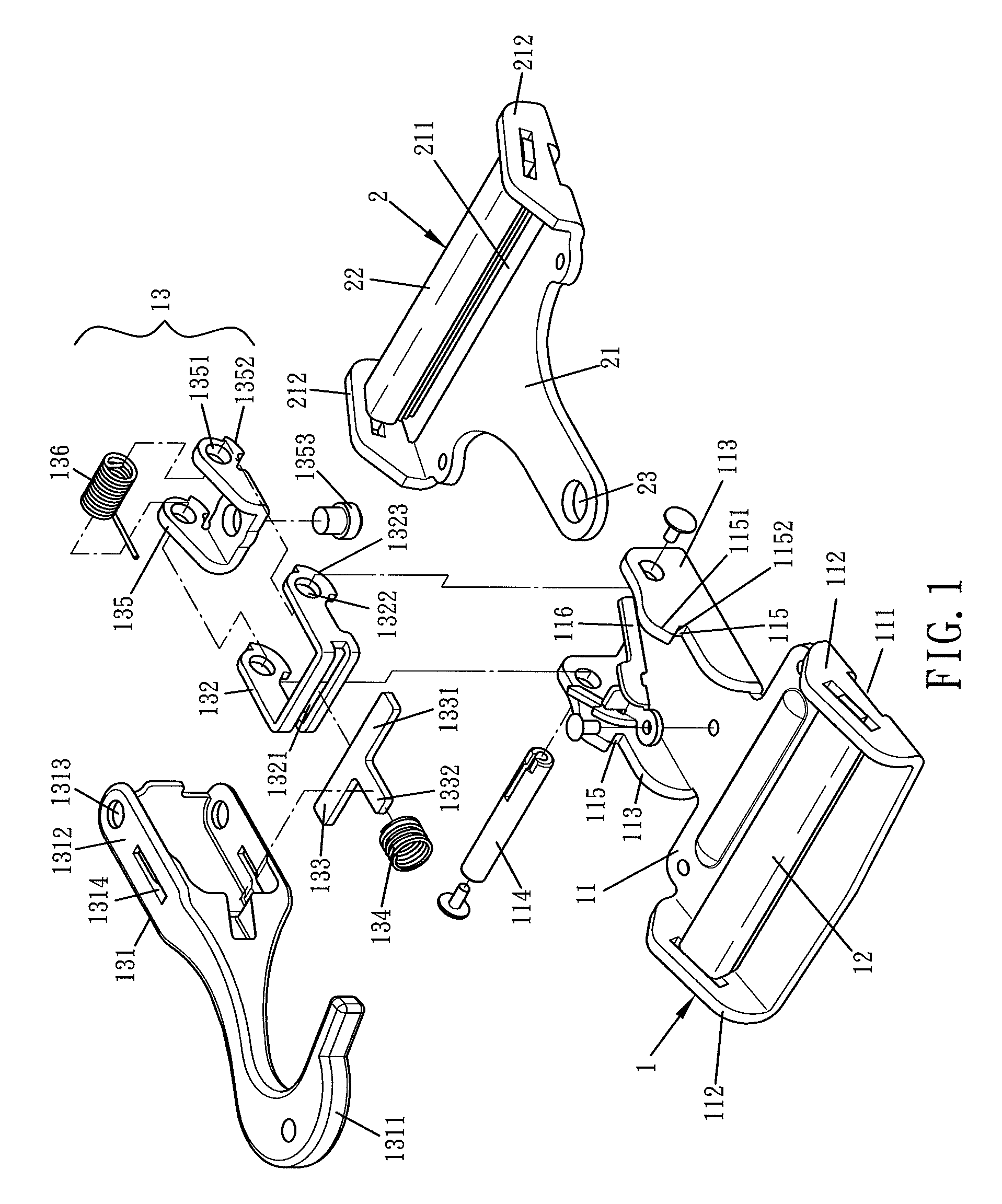
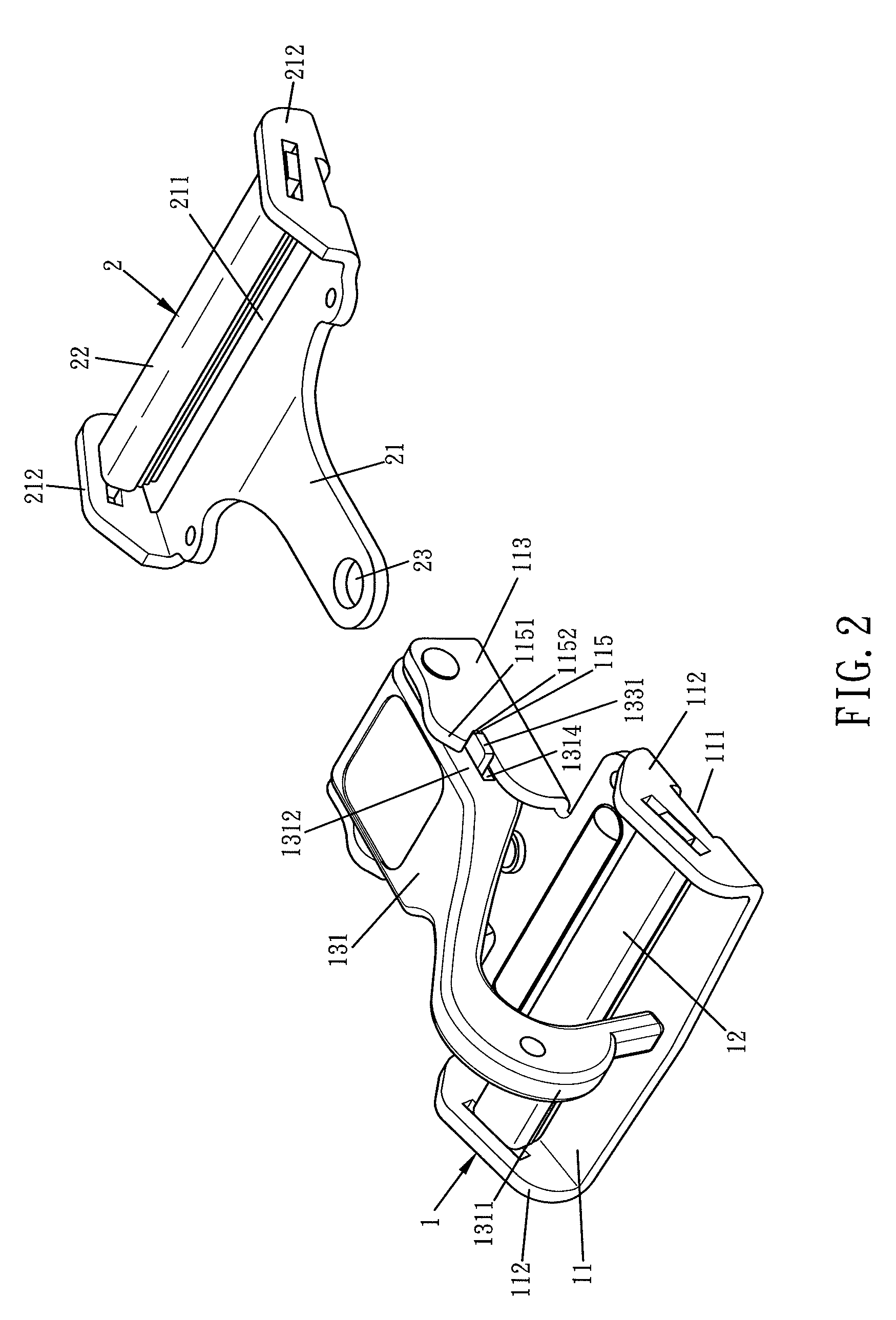
[0024]Referring to FIGS. 1-3, a buckling device for safety belts in accordance with a preferred embodiment of the present invention includes a buckle 1, and a fastening member 2. The buckle 1 is made of metal material and bent to form a projected holder 11. A wider segment of the holder 11 includes a laterally elongated hole 111 and two sides thereof are respectively bent to form a first side plates 112. Between two first side plates 112 is defined a sideable shaft 12, such that a side of the safety belt can be inserted to the buckle 1. On each of two sides of a narrower segment of the holder 11 is mounted a second side plate 113. Between two second side plates 113 is defined a locking unit 13 by using a shank 114. On an upper rim of the second si...


PUM


Abstract

A buckling device for safety belts includes a buckle made of metal material and bent to form a projected holder. A wider segment of the holder is used to insert a side of the safety belt to the buckle. On each of two sides of a narrower segment of the holder is mounted a second side plate. Between two second side plates is defined a locking unit by using a shank. On an upper rim of the second side plate is a recess. The locking unit includes an engagement member in which a rotary member, a fixing piece, a compression spring, a mounting member, and a torsion spring are received. A fastening member includes a bottom sheet, with a wider segment thereof being used to insert another side of the safety belt. The fastening member further includes a retaining pore secured on a narrower segment thereof.

Description

BACKGROUND OF THE INVENTION[0001]1. Field of the Invention[0002]The present invention relates to a buckling device and, more particularly, to a buckling device for a safety belt that can be used safely.[0003]2. Description of the Prior Art[0004]Conventional safety belts are used in general vehicles and racing cars. However, they have the following disadvantages:[0005]1. In buckling operation, the engagement member of the buckling device has to be rotated to a certain angle to insert the fastening member into the buckle, making operating inconvenient.[0006]2. The conventional buckling devices are buckled in a one-section operating manner to disengage the engagement member easily, causing unsafety in car crashes.[0007]3. The holder of the conventional buckles is forged, resulting in a heavy weight.[0008]The present invention has arisen to mitigate and / or obviate the afore-described disadvantages.SUMMARY OF THE INVENTION[0009]The primary object of the present invention is to provide a ...

Claims


Application Information

Patent Timeline
Patent Type & Authority Patents(United States)
IPC IPC(8): A44B11/25
CPCA44B11/2526Y10T24/45665Y10T24/4056Y10T24/404Y10T24/45639Y10T24/3423
Inventor WU, WEN-YUAN
Owner TAIWAN RACING PRODS
Why Eureka
Try Eureka