A concrete slump detection device and its detection method

A detection device and slump technology, applied in the direction of measuring devices, material inspection products, flow characteristics, etc., can solve the problems of affecting concrete slump formation, inaccurate measurement results, easy to touch concrete, etc., to increase the accuracy of measurement Sexuality and convenience, saving manpower, and detecting the effect of labor saving

Active Publication Date: 2018-04-06
海南方能测试技术有限公司
View PDF8 Cites 1 Cited by
  • Summary
  • Abstract
  • Description
  • Claims
  • Application Information

AI Technical Summary

Problems solved by technology

Some existing concrete slump detection devices often need to manually operate various links. It is easy to touch the concrete during the pull-up process, which affects the concrete slump shape, and the measurement process is also prone to large deviations, resulting in inaccurate measurement results. Repeatability is poor, so there is an urgent need for a concrete slump detection device that can solve the above technical problems

Method used


Image

  • A concrete slump detection device and its detection method
  • A concrete slump detection device and its detection method
  • A concrete slump detection device and its detection method

Examples


Embodiment 1

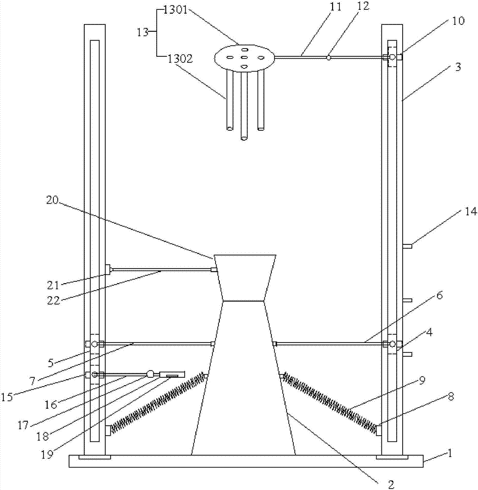
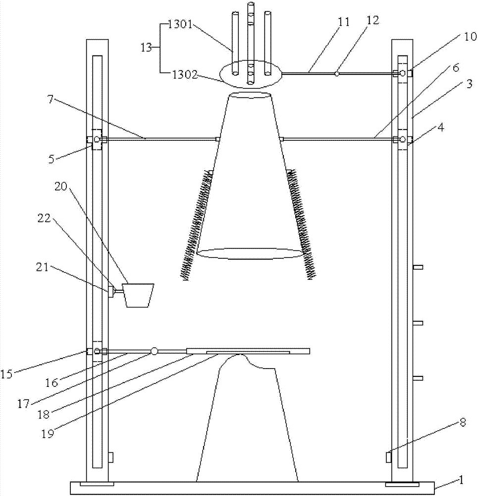
[0031] Such as Figure 1~2As shown, a concrete slump detection device includes a platform 1, a slump bucket 2 and two slide rails 3, the slump bucket 2 is placed at the center of the platform 1, and the two slide rails 3 are arranged On both sides of the slump bucket 2, fixed on the platform 1, that is, two slide rails 3 are arranged on both sides of the center line of the platform 1, the platform 1 has a larger space, and the slump bucket 2 and the two slide rails There is enough space between rails 3 to allow the concrete to slump naturally without any shelter. The two slide rails 3 are respectively provided with a first slide block 4 and a second slide block 5, and the slide rails 3 are provided with a switch for controlling the first slide block 4 and the second slide block 5, and the first slide block 4. The second slider 5 is respectively connected with a first lifting rod 6 and a second lifting rod 7, the side of the slump barrel 2 is provided with a connecting port, t...

Embodiment 2

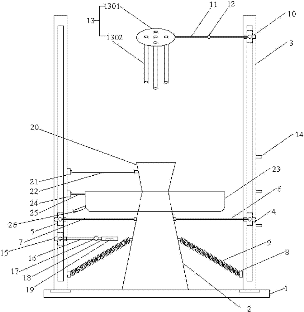
[0039] like Figure 3-5 As shown, the difference between this embodiment and Embodiment 1 is that it also includes an excess material trough 23, which is a U-shaped groove, and a second rotating head 24 is provided on the side of one of the slide rails 3, and the second rotating head 24 is provided on the side of the first slide rail 3. The second rotating head 24 is connected with the fourth connecting rod 25, and the fourth connecting rod 25 is connected with the residual material tank 23, and the side of the residual material tank 23 is provided with an inclined outlet 26. The structure and connection design of the residual material chute 23 can better undertake the excess concrete in the cutting process. There is a gap in the U-shaped groove, which is convenient to tightly trap the slump barrel 2 horizontally, the second rotating head 24 and the fourth connecting rod 25 are convenient for the remaining material tank 23 to trap horizontally or stay away from the slump barre...


PUM


Abstract

The invention discloses a concrete slump detection device which comprises a platform, a slump barrel and two slide rails, wherein the two slide rails are distributed on two sides of the slump barrel and fixed to the platform; a first slide block, a second slide block, a third slide block and a fourth slide block are arranged on the two slide rails respectively, two slide blocks are respectively connected with a first lifting rod and a second lifting rod, and the two lifting rods are detachably connected with the slump barrel; holes are formed in the lower ends of the two slide rails respectively, spring parts are arranged on the two sides of the slump barrel respectively, and the tail ends of the spring parts are detachably connected with the holes; the third slide block is connected with a first connection rod containing a first rotating shaft, the first connection rod is connected with a material shaking part, and a plurality of limiting clamp blocks are arranged on the lateral sides of the corresponding slide rail; the fourth slide block is connected with a second connection rod containing a second rotating shaft, the second connection rod is connected with a stopping plate, a humidity sensor is arranged at the bottom of the stopping plate, and scales are arranged on the corresponding slide rail. The concrete slump detection device disclosed by the invention can save more labor in detection, reduce artificial error and more greatly improve measurement accuracy.

Description

technical field [0001] The invention relates to the technical field of concrete detection, in particular to a concrete slump detection device and a detection method thereof. Background technique [0002] Concrete slump mainly refers to the plasticizing performance and pumpability of concrete. Factors affecting concrete slump mainly include gradation change, water content, weighing deviation of weighing apparatus, dosage of admixture and temperature of cement, etc. The slump of concrete should be determined according to the structural section of the building, steel bar content, transportation distance, pouring method, transportation mode, vibration capacity and climate. When selecting the mix ratio, it should be considered comprehensively, and the smaller one should be adopted. of slump. The basic test method of slump is to use a trumpet-shaped slump bucket with an upper mouth of 100mm, a lower mouth of 200mm, and a height of 300mm, pour concrete into it and compact it, and ...

Claims


Application Information

Patent Timeline
Patent Type & Authority Patents(China)
IPC IPC(8): G01N33/38G01N11/00
CPCG01N11/00G01N33/383
Inventor 王定梧王东明袁锋
Owner 海南方能测试技术有限公司
Why Eureka
Try Eureka