Paying-off device

A pay-off device and bobbin technology, which is applied in the directions of transportation and packaging, thin material handling, and delivery of filamentous materials, etc., can solve the problems of high labor intensity, difficulty in unwinding, and unsightly appearance, and achieve beautiful structure and structure Simple, stable effect

Pending Publication Date: 2017-12-15
稳健医疗用品(荆门)有限公司
View PDF8 Cites 4 Cited by
  • Summary
  • Abstract
  • Description
  • Claims
  • Application Information

AI Technical Summary

Problems solved by technology

[0002] When the coiled wire is paid out from the inner ring, the wire is not straight, and each ring of wire will produce a certain deflection. When the wire is released from the outer ring, the coil must be artificially rotated in the opposite direction of the winding, which is slow and labor-intensive. And rest assured that it is not beautiful
For single-phase electricity, at least two wires are laid out at the same time, and it is more difficult to pay off, while for three-phase lines, it is more difficult to pay out at least three wires.

Method used


Image

  • Paying-off device
  • Paying-off device
  • Paying-off device

Examples


Embodiment Construction

[0024] The principles and features of the present invention will be described below with reference to the accompanying drawings. The examples cited are only used to explain the present invention and not used to limit the scope of the present invention.

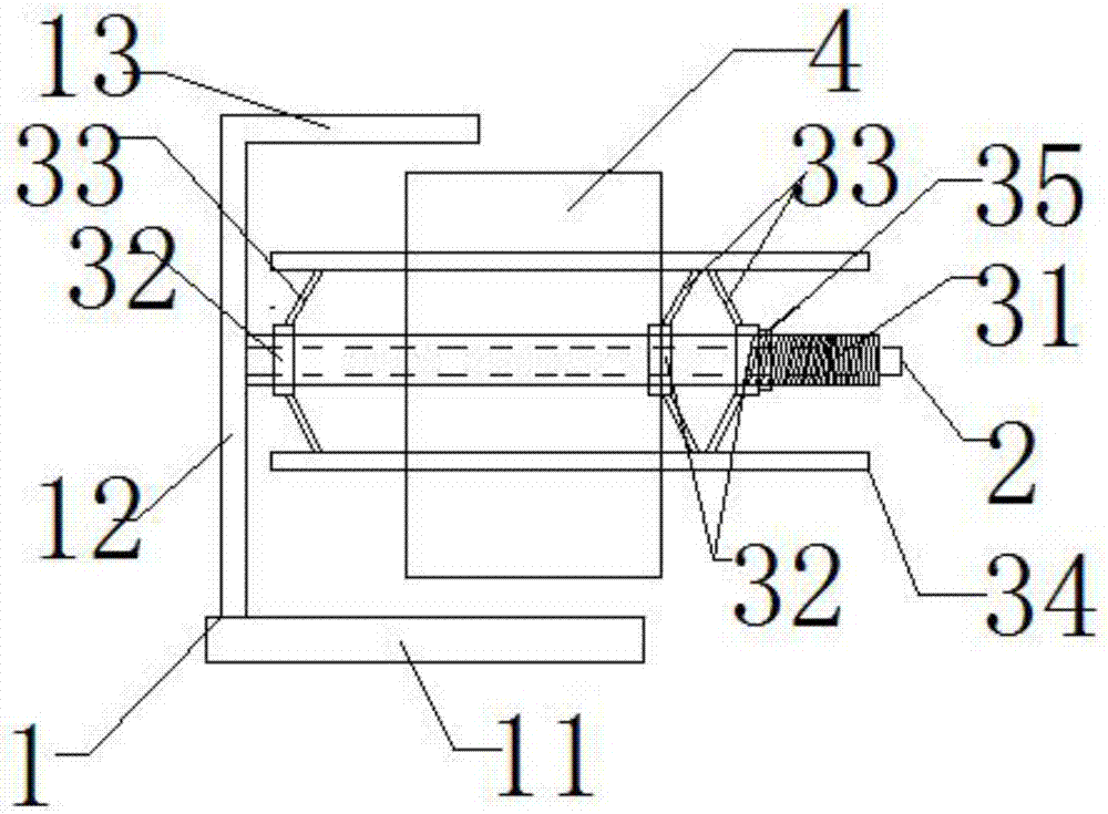
[0025] Such as figure 1 As shown, this embodiment provides a wire pay-off device, which includes a bracket 1, a rotating shaft 2 and a spool 3. The bracket 1 includes a horizontally arranged base 11 and a vertical arm 12 vertically arranged above the base 11. The rotating shaft 2 is arranged horizontally and one end is fixed on the vertical arm 12, the middle of the spool 3 is provided with a coaxial through hole, and the spool 3 is rotatably fitted outside the rotating shaft 2 through the coaxial through hole; 3 Set the coil 4 with the above.

[0026] In the above-mentioned embodiment, the upper end of the vertical arm 12 is further provided with a handle 13, the handle 13 is a cross bar, and the handle 13 is horizontally fixed to...


PUM


Abstract

The invention discloses a paying-off device. The paying-off device comprises a support, a rotary shaft and a reel, wherein the rotary shaft is horizontally arranged, one end of the rotary shaft is fixed to the support, the reel is arranged outside the rotary shaft and is capable of rotating relative to the rotary shaft, and the reel is sleeved with a coil. According to the paying-off device, through arrangement of the reel, the coil is arranged on the reel in a sleeving mode, the outer end of the coil is pulled during paying-off, and the coil and the reel rotate around the rotary shaft to pay off a wire one circle by one circle; and besides, a plurality of wire coils can be disposed on the reel side by side to be paid off at the same time, operation is convenient and quick, wire intertwining is avoided, and the complete paying-off work can be completed by one person.

Description

Technical field [0001] The invention relates to a wire pay-off device, which belongs to the field of electrical equipment, in particular to a wire pay-off device capable of not being rolled up when the wire is paid off. Background technique [0002] When the coiled wire is unwound from the inner circle, the wire is not straight, and each loop of the wire will produce a certain degree of deflection. When unwinding the wire from the outer circle, the coil should be manually rotated in the opposite direction of the winding, which is slow and labor-intensive. And rest assured that it is not beautiful. However, it is more difficult to pay out at least two wires for single-phase electricity at the same time, and it is more difficult to pay out at least three wires for three-phase lines. Summary of the invention [0003] In order to solve the above-mentioned technical problems, the purpose of the present invention is to provide a wire pay-off device that can fix the coil and can pay off...

Claims


Application Information

Patent Timeline
Patent Type & Authority Applications(China)
IPC IPC(8): B65H49/30
CPCB65H49/30
Inventor 纪华
Owner 稳健医疗用品(荆门)有限公司
Why Eureka
Try Eureka