Automatic boring equipment for engine cylinder head

An engine cylinder, drilling equipment technology, applied in drilling/drilling equipment, boring/drilling, metal processing equipment and other directions, can solve the problems of inconvenient operation, low production efficiency, time-consuming, etc., to ensure smoothness and dimensional accuracy, stable and reliable clamping, and the effect of speeding up production

Pending Publication Date: 2019-01-15
开平市宝缸精密机械有限公司
View PDF0 Cites 2 Cited by
  • Summary
  • Abstract
  • Description
  • Claims
  • Application Information

AI Technical Summary

Problems solved by technology

Usually the cylinder head is made of aluminum casting, and then undergoes processes such as boring, processing the end face, and drilling the outer mounting hole. There are many outer mounting holes, and it is difficult to clamp the cylinder head. On the one hand, the shape of the cylinder head is irregular. On the other hand, the inner hole has high requirements for smoothness and precision, so it cannot be used as a force-bearing surface for clamping.
As a result, the existing drilling machine must undergo multiple clamping and replacement of the drill bit to complete the drilling of the outer mounting hole of the cylinder head, which is inconvenient to operate, low in production efficiency, and time-consuming

Method used


Image

  • Automatic boring equipment for engine cylinder head
  • Automatic boring equipment for engine cylinder head
  • Automatic boring equipment for engine cylinder head

Examples


Embodiment Construction

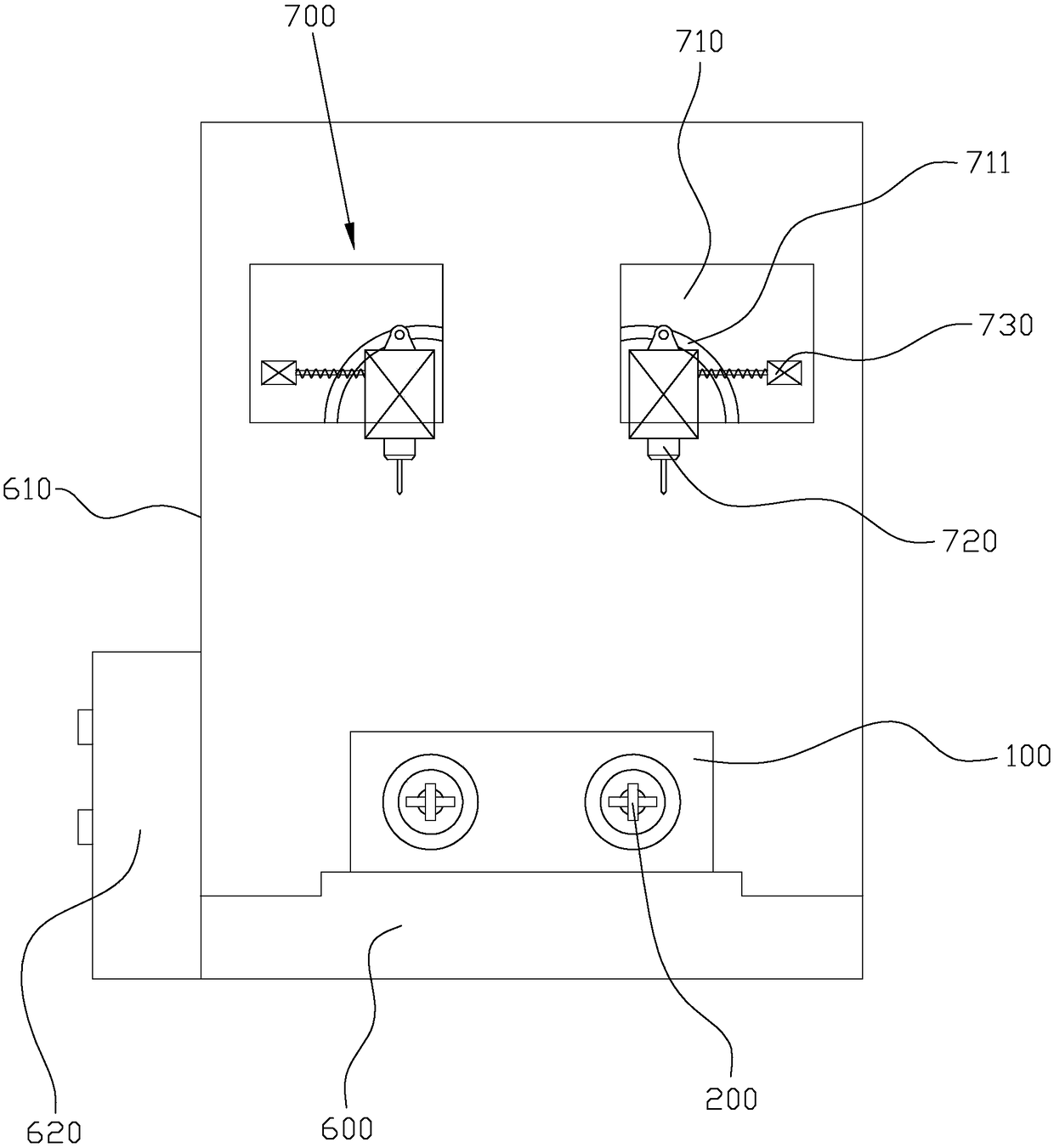
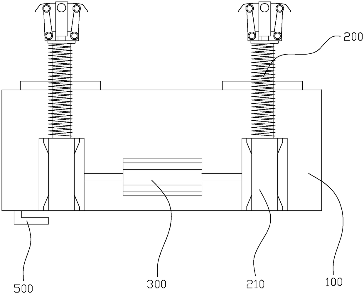
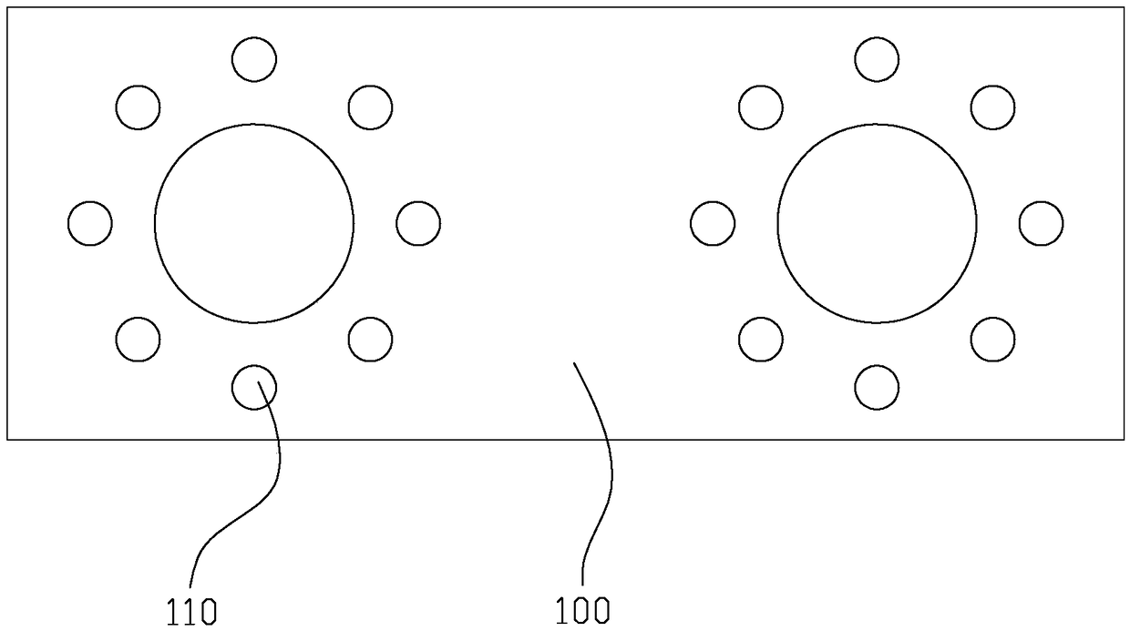
[0020] refer to Figure 1 to Figure 4 , an embodiment of the present invention provides an engine cylinder head automatic drilling equipment, including a main frame 600, the main frame 600 is provided with a clamp, two sets of drill assemblies located above the clamp, and an outer casing 610, the drill The assembly includes a mounting frame 710, a drill bit 720 and a driving device 730. The middle part of the drill bit 720 is hinged on the mounting frame 710. The mounting frame 710 is provided with an arc-shaped groove 711. The slider in the arc-shaped groove 711, the driving device 730 is connected to the drill bit 720 and drives the drill bit 720 to swing; the clamp includes a base 100, two locking assemblies 200 and a steering device 300, and the locking assembly 200 includes a telescopic cylinder 210, a guide sleeve 220, a telescopic rod 230 and two locking blocks 240, the guide sleeve 220 is fixed on the telescopic cylinder 210, and the telescopic rod 230 is connected thr...


PUM


Abstract

Embodiment of the present invention discloses automatic boring equipment for an engine cylinder head, and the equipment comprises a main unit platform, and the main unit platform is provided with a clamping tool, a drill bit assembly located above the clamping tool, and a housing. The drill bit assembly includes a mounting bracket, a drill bit, and a driving device. The middle portion of the drillbit is hinged to the mounting bracket, and the mounting bracket is provided with an arc-shaped groove. The drill bit is provided with a sliding block that is clamped in the arc-shaped groove. The driving device is connected with the drill bit and drives the drill bit to swing. The clamping tool comprises a base, two locking components and a steering device, and each locking component comprises atelescopic cylinder, a guiding sleeve, a telescopic rod and two locking blocks. The steering device and the telescopic cylinder are arranged in the base, and the steering device is connected with thetwo locking components and pushes the two locking components to rotate. The telescopic rod is arranged outside the base. The drill bit assembly and the clamping device cooperate with each other to complete the drilling of all the outer mounting holes of the cylinder head in one time, thereby achieving the full-automatic production.

Description

technical field [0001] The invention relates to the technical field of drilling equipment, in particular to an automatic drilling equipment for an engine cylinder head. Background technique [0002] With the progress of the times, motorcycles have entered thousands of households and are loved by the majority of the people. In the production of motorcycles, the production process of the cylinder head of the engine requires high requirements and many steps. Usually the cylinder head is made of aluminum casting, and then undergoes processes such as boring, processing the end face, and drilling the outer mounting hole. There are many outer mounting holes, and it is difficult to clamp the cylinder head. On the one hand, the shape of the cylinder head is irregular. On the other hand, the inner hole requires high smoothness and precision, so it cannot be used as a force-bearing surface for clamping. As a result, the existing drilling machine must undergo multiple clamping and rep...

Claims


Application Information

Patent Timeline
Patent Type & Authority Applications(China)
IPC IPC(8): B23B39/16B23Q3/08B23Q3/00B23Q1/44
CPCB23B39/16B23Q1/44B23Q3/00B23Q3/08
Inventor 王湘甫
Owner 开平市宝缸精密机械有限公司
Why Eureka
Try Eureka