Ball valve machining equipment

A processing equipment, ball valve technology, applied in metal processing equipment, grinding/polishing equipment, working carrier, etc., can solve the problems of single product, low processing efficiency, unable to fix and grind the valve core and valve seat, etc.

Active Publication Date: 2019-01-18
江山市志成阀门有限公司
View PDF9 Cites 2 Cited by
  • Summary
  • Abstract
  • Description
  • Claims
  • Application Information

AI Technical Summary

Problems solved by technology

[0004] Although the grinding mechanism in the above-mentioned documents grinds the valve core and the valve seat, the degree of cooperation between the valve core and the valve seat is high, and the sealing performance of the produced ball valve is improved, but the equipment is in the process of working. , the equipment can only grind a set of valve core and valve seat with a certain specification, but in the actual processing process, because the specifications of the ball valve are different, the specifications of the valve core and valve seat in different ball valves are also different. Obviously, the above equipment It is not possible to fix and grind valve cores and valve seats of different specifications and sizes. The products produced are single and the processing efficiency is low.

Method used


Image

  • Ball valve machining equipment
  • Ball valve machining equipment
  • Ball valve machining equipment

Examples


Embodiment Construction

[0039] In order to enable those skilled in the art to better understand the solutions of the present invention, the technical solutions in the embodiments of the present invention will be clearly and completely described below in conjunction with the drawings in the embodiments of the present invention.

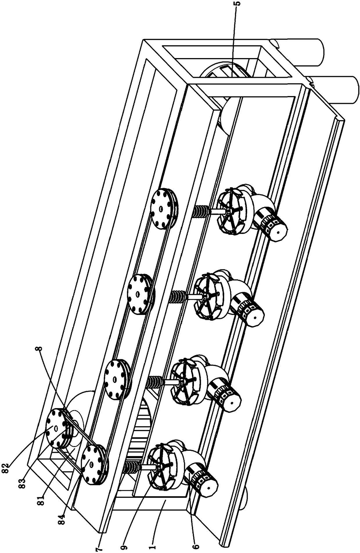
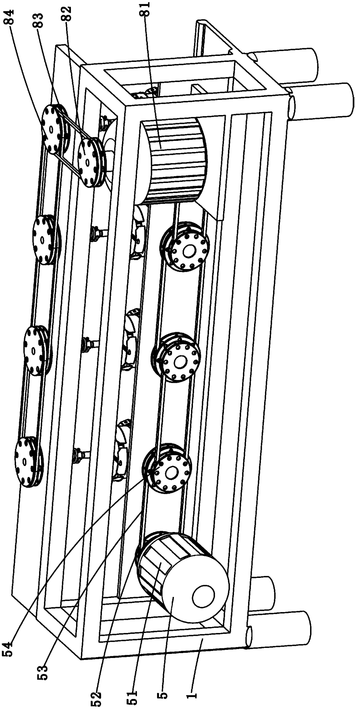
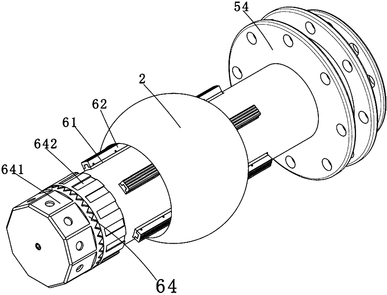
[0040] Such as Figure 1-14 As shown, the present invention discloses a ball valve processing equipment, including a frame 1, a first fixing part 4, a first driving part 5, a clamping structure 6, a second fixing part 7, a clamping structure 8 and a second driving Components 9, wherein the frame 1 is a metal frame body, the first and second driving components are all arranged on the frame 1; the first fixing part 4 is a metal rod, and the first fixing The tail end of the part 4 is connected with the bottom of the frame 1 through a bearing part, so the first fixing part 4 can rotate freely relative to the frame 1; the first driving part 5 is used to drive the first The fixed ...


PUM


Abstract

The invention discloses ball valve machining equipment. The equipment comprises valve cores with medium flow passages, valve bases matched with the outer walls of the valve cores, a rack, first fixingassemblies penetrating through the medium flow passages, a first driving assembly for driving the first fixing assemblies to rotate longitudinally, first clamping structures disposed on the first fixing assemblies, second fixing assemblies, second clamping structures disposed on the second fixing assemblies and a second driving assembly. The first clamping structures firmly abut against the innerwalls of the medium flow passages to fix the valve cores; the second clamping structures are used for clamping the valve bases to make the valve bases be in contact with the valve cores; the second driving assembly is used for driving the second fixing assemblies to rotate in order to drive the valve bases to be in friction with the valve cores. The valve bases different in specification and sizeand the valve cores different in specification and size are clamped by the same equipment; therefore, in the process of machining the valve bases and the valve cores, various matched valve bases andvalve cores can be machined by the same equipment at the same time, the machining efficiency is high, and the cost required by the equipment is reduced.

Description

technical field [0001] The invention belongs to the technical field of valve pipelines, and in particular relates to a processing technology and processing equipment of a ball valve. Background technique [0002] Ball valves are widely used in petroleum refining, long-distance pipelines, chemical industry, papermaking, pharmaceuticals, water conservancy, electric power and other industries. They are widely used in the market. The current ball valves include valve bodies and valve cores with medium flow channels , valve seat, valve stem and other components, which rotate the valve core through the valve stem to realize the opening and closing of the ball valve. [0003] Chinese patent CN105729270B discloses a valve core valve seat grinding mechanism, including: a first installation frame, with a first installation space suitable for installing the valve seat, and a first air hole communicating with the first installation space and the atmosphere; the second installation frame...

Claims


Application Information

Patent Timeline
Patent Type & Authority Applications(China)
IPC IPC(8): B24B37/27
CPCB24B37/27B24B47/22
Inventor 张志荣
Owner 江山市志成阀门有限公司
Why Eureka
Try Eureka