Oil injecting equipment

An oil injection equipment and oil injection technology, which is applied in the direction of mechanical equipment, lubricating oil control valves, lubricating parts, etc., can solve the problems of low efficiency, less oil storage, uneven distribution of oil, etc., and achieve high work efficiency, uniform distribution, The effect of uniform and controllable oil volume

Active Publication Date: 2017-12-15
HUNAN SANTER MACHINERY MFG
View PDF7 Cites 1 Cited by
  • Summary
  • Abstract
  • Description
  • Claims
  • Application Information

AI Technical Summary

Problems solved by technology

This manual oil brushing method is not only inefficient, but also has less oil storage between the shaft and the bushing, and the oil distribution is uneven

Method used


Image

  • Oil injecting equipment
  • Oil injecting equipment
  • Oil injecting equipment

Examples


Embodiment Construction

[0022] In order to enable those skilled in the art to better understand the technical solutions in the present application, the technical solutions in the embodiments of the present application will be clearly and completely described below in conjunction with the drawings in the embodiments of the present application. Obviously, the described The embodiments are only some of the embodiments of the present application, but not all of them. Based on the embodiments in this application, all other embodiments obtained by persons of ordinary skill in the art without creative efforts shall fall within the scope of protection of this application.

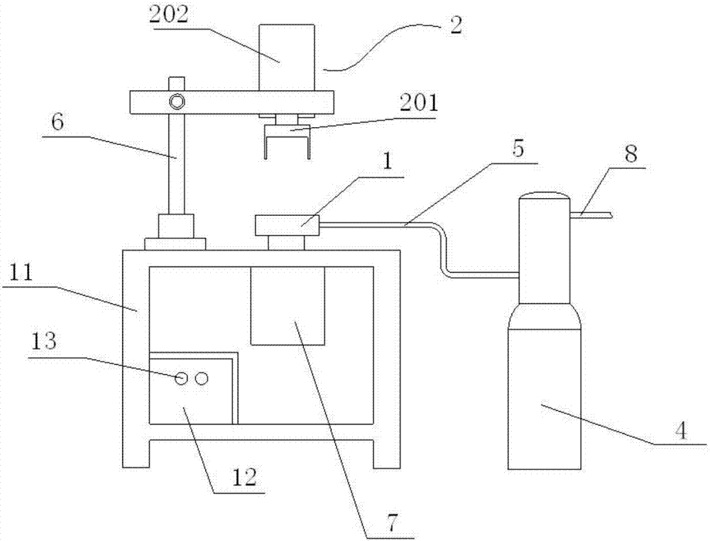
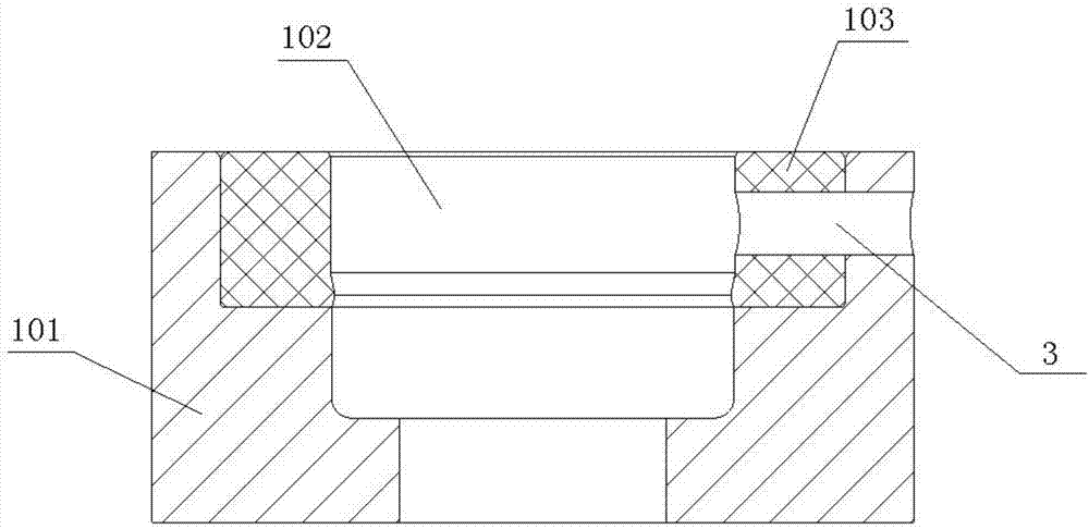
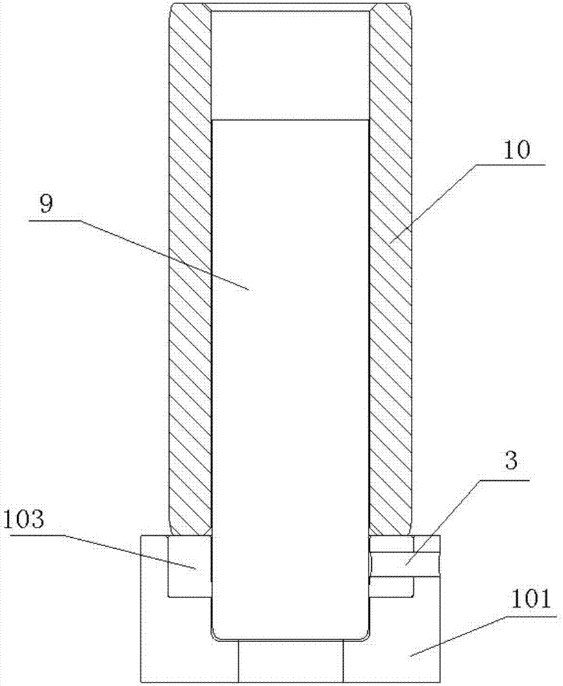
[0023] First of all, it needs to be explained that this application does not limit the position and direction of the clamping seat 1 and the clamping cover 2. The clamping seat 1 and the clamping cover 2 can be arranged up and down, or arranged horizontally, left and right, etc.; and the clamping seat The relative position of 1 and the cl...


PUM


Abstract

The application discloses oil injecting equipment. The oil injecting equipment comprises a clamping mechanism and an oil injecting mechanism; the clamping mechanism comprises a clamping seat and a clamping cover; the clamping cover and the clamping seat and are matched and are used for clamping two ends of each of a shaft sleeve and a shaft; an oil injecting port is formed in the clamping seat and is used for injecting oil to the position between shaft and the shaft sleeve; the oil injecting mechanism comprises an oil tank and an oil injecting power part; the oil injecting part communicates with the oil injecting port through an oil way; and the oil injecting power part is used for outputting lubricating oil from the oil tank through the oil way. According to the oil injecting equipment, the assembled shaft and shaft sleeve are only required to be placed between the clamping seat and the clamping cover, the two ends of each of the shaft and the shaft sleeve are clamped by matching the clamping cover and the clamping seat, then, the oil injecting power part is started to output the lubricating oil from the oil tank through the oil way and inject the lubricating oil to the position between the shaft and the shaft sleeve from the oil injecting port, so that automatic oil injecting is realized; the work efficiency is high; the injected oil amount is controllable; and grease is uniformly distributed between the shaft and the shaft sleeve.

Description

technical field [0001] The invention belongs to the technical field of lubricating oil injection, and in particular relates to an oil injection device. Background technique [0002] During the use of the chain track, the friction between the shaft and the bushing will cause wear and tear. In order to reduce the friction between the shaft and the bushing and prolong the service life of the chain rail, it is necessary to add a certain amount of lubricating grease between the shaft and the bushing before installation. The existing method of adding lubricating oil between the shaft and the shaft sleeve of the chain rail is to take the shaft out of the shaft sleeve, manually brush the shafts one by one, and then put the oiled shafts into the shaft sleeve Inside. This manual oil brushing method is not only inefficient, but also has less oil storage between the shaft and the bushing, and the oil distribution is uneven. Contents of the invention [0003] In view of the problems...

Claims


Application Information

Patent Timeline
Patent Type & Authority Applications(China)
IPC IPC(8): F16N11/08F16N11/10F16N23/00F16N29/04F16N29/02F16N27/00F16N21/04
CPCF16N11/08F16N11/10F16N21/04F16N23/00F16N27/00F16N29/02F16N29/04
Inventor 邱宝珠艾华杰刘海雄
Owner HUNAN SANTER MACHINERY MFG
Why Eureka
Try Eureka