Chain rotary type conveying line

A conveyor line, rotary technology, applied in the direction of conveyor, transportation and packaging, can solve the problem that the transfer pallet cannot be rotated by the chain.

Pending Publication Date: 2017-12-19
STON ROBOT CHANGZHOU
View PDF6 Cites 5 Cited by
  • Summary
  • Abstract
  • Description
  • Claims
  • Application Information

AI Technical Summary

Problems solved by technology

[0003] The technical problem to be solved by the present invention is: in order to solve the problem that the transfer pallet cannot rotate with the chain in the prior art, a chain rotary conveyor line is now provided

Method used


Image

  • Chain rotary type conveying line
  • Chain rotary type conveying line
  • Chain rotary type conveying line

Examples


Embodiment 1

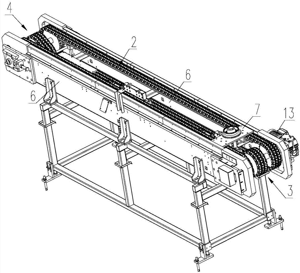
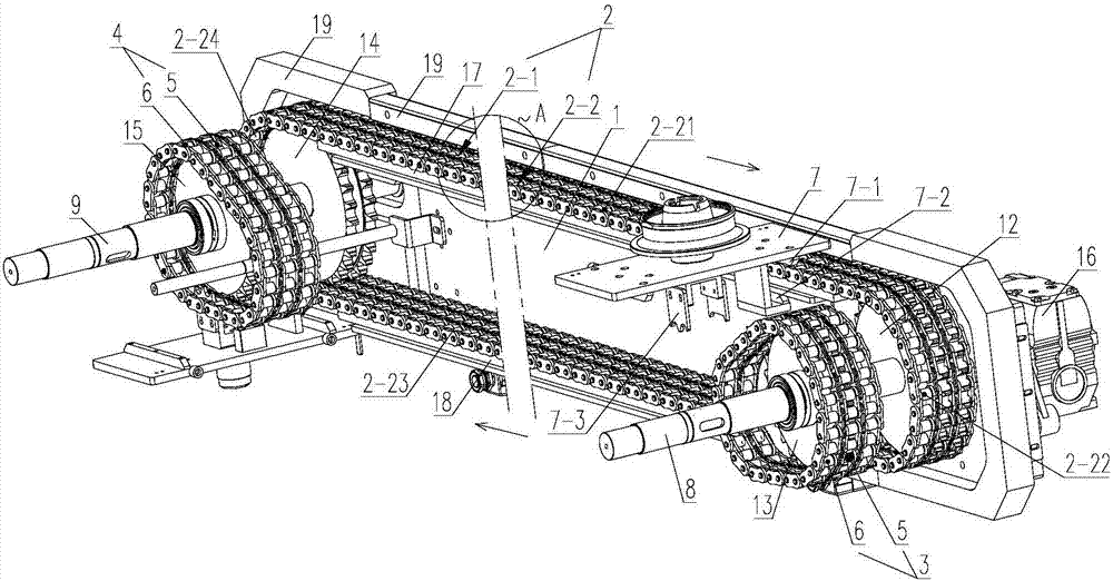
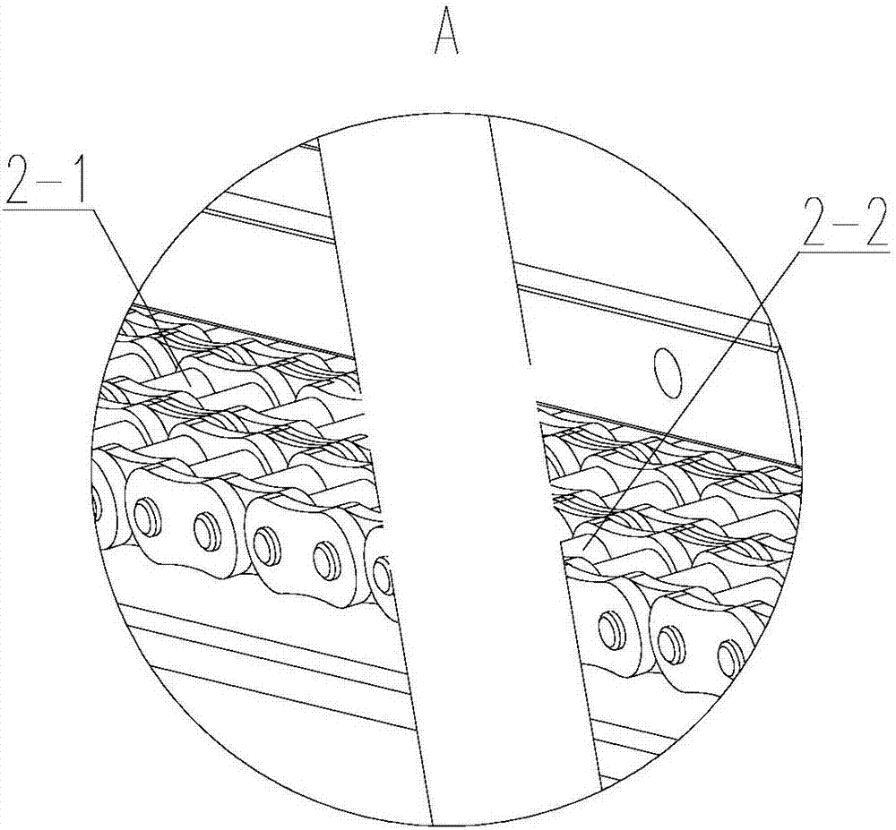
[0027] Such as Figure 1-9 As shown, a chain rotary conveyor line includes a closed conveyor chain group 2, a head-end drive chain group 3 and a tail-end drive chain group 4, and the conveyor chain group 2 includes parallel conveyor transmission chains 2-1 and conveyor The support chain 2-2, the head-end drive chain group 3 and the tail-end drive chain group 4 all include a parallel steering drive chain 5 and a steering drive chain 6, and the conveying support chain 2-2 includes conveying sections 2-21 connected end to end in sequence , the downward steering section 2-22, the feeding section 2-23 and the upward steering section 2-24, the steering transmission chain 5 and the conveying transmission chain 2-1 are all driven by external force, and the conveying section 2-21 and the feeding section 2 -23 all extend along the horizontal direction and are parallel to each other. The conveying section 2-21, the downward diversion section 2-22, the return section 2-23 and the upward d...


PUM


Abstract

The invention relates to the technical field of rotary conveying devices, in particular to a chain rotary type conveying line. The chain rotary type conveying line comprises conveying chain sets, a head end driving chain set and a tail end driving chain set, wherein the conveying chain sets, the head end driving chain set and the tail end driving chain set are all closed; each conveying chain set comprises a conveying transmission chain and a conveying supporting chain which are connected in parallel; the head end driving chain set and the tail end driving chain set each comprise a steering transmission chain and a steering driving chain which are connected in parallel; and each conveying supporting chain comprises a conveying section, a descending steering section, a return section and an ascending steering section which are connected end to end in sequence. According to the chain rotary type conveying line, when a transferring supporting plate passes through the descending steering sections and the ascending steering sections, a drive tooth at the lower part of the transferring supporting plate meshes with the corresponding steering driving chain so as to provide forward movement power for the transferring supporting plate, a second guiding strip abuts against the inner side of the conveying supporting chains so as to enable the transferring supporting plate to smoothly pass through the ascending steering sections and the descending steering sections, and therefore rotation of the transferring supporting plate on the conveying line can be realized.

Description

technical field [0001] The invention relates to the technical field of rotary conveying devices, in particular to a chain rotary conveying line. Background technique [0002] The rotary conveyor device is often used in automatic production equipment. The existing chain rotary conveyor line is to place the transfer pallet for placing the workpiece directly on the chain. The output end of the chain rotary conveyor line outputs the workpiece on the transfer pallet, and the transfer pallet rotates with the chain. Since the transfer pallet is directly placed on the chain, when the transfer pallet turns downward, the transfer pallet cannot be reused. Gravity is supported on the chain, so the transfer pallet cannot turn around with the chain. Contents of the invention [0003] The technical problem to be solved by the present invention is: in order to solve the problem in the prior art that the transfer pallet cannot rotate with the chain, a chain rotary conveyor line is now pro...

Claims


Application Information

Patent Timeline
Patent Type & Authority Applications(China)
IPC IPC(8): B65G17/38B65G23/06
CPCB65G17/38B65G23/06
Inventor 刘金石张有斌
Owner STON ROBOT CHANGZHOU
Why Eureka
Try Eureka