
Ventilated window frame

A window frame and outer frame technology, applied in the field of windows, can solve problems such as poor ventilation, poor rain protection of windows, and insufficient space

Inactive Publication Date: 2017-12-19
时亮
View PDF0 Cites 2 Cited by
  • Summary
  • Abstract
  • Description
  • Claims
  • Application Information

AI Technical Summary

Problems solved by technology

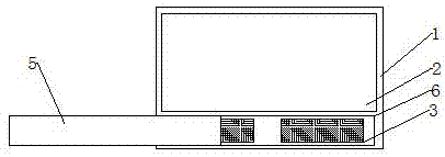
[0002] In architecture, windows refer to openings built on walls or roofs to allow light or air to enter the room. Most of the windows are of the casement or sliding sliding type. Such windows are not good at blocking rain, and some There is not enough space in the place, and it is not convenient to open windows, which will lead to poor ventilation

Method used


Image

  • Ventilated window frame
  • Ventilated window frame

Examples


Embodiment Construction

[0012] The present invention will be further described below in conjunction with the accompanying drawings.

[0013] Such as figure 1 and figure 2 As shown, the breathable window frame includes an outer frame 1, an inner window 2 and a sliding plate 5. The lower end of the outer frame 1 has two vents 3 and a slide rail 6, and the sliding plate 5 passes through the slide rail 6 and the outer frame 1. Flexible connection, two rain shields 4 are arranged on one side of the outer frame 1.

[0014] The material of the outer frame 1 is an aluminum-plastic profile.

[0015] The inside of the air vent 3 is provided with a PM2.5 filter screen and a layer of activated carbon filter screen.

[0016] A layer of glass is inlaid in the described inner window 2 .

[0017] When in use, the glass window is installed, and whether to push the movable plate is selected according to actual needs.


PUM


Abstract

The present invention is a breathable window frame, which comprises an outer frame, an inner window and a sliding plate. The lower end of the outer frame has two air vents and a slide rail. The sliding plate is movably connected to the outer frame through the slide rails. One side of the outer frame There are two rain-shielding boards; the invention has beautiful appearance, good rain-shielding performance and does not take up space.

Description

technical field [0001] The invention relates to a window, in particular to a breathable window frame. Background technique [0002] In architecture, windows refer to openings built on walls or roofs to allow light or air to enter the room. Most of the windows are of the casement or sliding sliding type. Such windows are not good at blocking rain, and some There is not enough space in the place, and it is not convenient to open windows, which will lead to poor ventilation. Contents of the invention [0003] Aiming at the above-mentioned problems in the prior art, the present invention provides a breathable window frame, which is beautiful in appearance and good in rain-proof performance, and can be directly ventilated without opening the window. [0004] In order to achieve the above object, the present invention is achieved through the following technical solutions: a breathable window frame, including an outer frame, an inner window and a sliding plate, the lower end of ...

Claims


Application Information

Patent Timeline
Patent Type & Authority Applications(China)
IPC IPC(8): E06B7/10E06B7/26
CPCE06B7/10E06B7/26
Inventor 时亮
Owner 时亮
Learn More