Stamping device capable of receiving materials conveniently

A discharging device and convenient technology, applied in the field of stamping devices, can solve the problems of reducing work efficiency and the like

Inactive Publication Date: 2017-12-22
青岛万沅金属制品有限公司
View PDF0 Cites 4 Cited by
  • Summary
  • Abstract
  • Description
  • Claims
  • Application Information

AI Technical Summary

Problems solved by technology

[0004] However, in the prior art, the stamped parts need to be manually taken out from the stamping groove, and then they can be stamped again, which reduces the work efficiency

Method used


Image

  • Stamping device capable of receiving materials conveniently
  • Stamping device capable of receiving materials conveniently
  • Stamping device capable of receiving materials conveniently

Examples


Embodiment Construction

[0034] The present invention will be described in further detail below in conjunction with the accompanying drawings. Wherein the same components are denoted by the same reference numerals. It should be noted that the words "front", "rear", "left", "right", "upper" and "lower", "bottom" and "top" used in the following description refer to the Directions, the words "inner" and "outer" refer to directions toward or away from, respectively, the geometric center of a particular component.

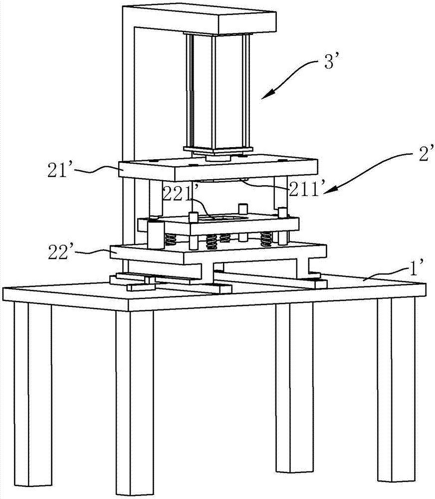
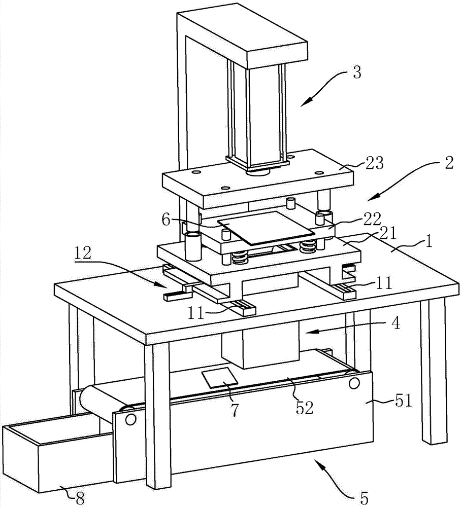
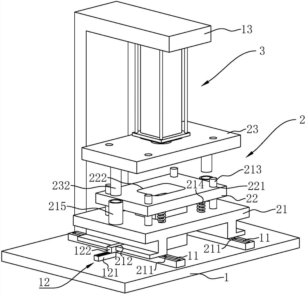
[0035] A stamping device for convenient material collection, such as figure 2 As shown, it includes a console 1, a stamping die 2 arranged on the console 1, a hydraulic cylinder 3 erected above the stamping die 2, a guideway 4 arranged under the stamping die 2, and a guideway 4 arranged at the end of the guideway 4 Transmission device 5. The punching device 2 uses the hydraulic cylinder 3 as the power to punch the plate 6 , and the punched parts 7 fall on the conveying device 5 through the ...


PUM


Abstract

The invention discloses a stamping device convenient for receiving materials. The key point of the technical scheme is to include an operating table and a stamping die arranged on the operating table. The stamping die includes a base, a lower template assembled on the base, and an The upper template, the lower template is vertically provided with a discharge port, and a guideway extends downward from the discharge port, the guideway is composed of an inner wall and an outer wall surrounding the inner wall, and the inner wall It is composed of four split side plates, and a compression spring is connected between the side plates and the outer wall, so that the stamping parts can be collected neatly by themselves without manual retrieving.

Description

technical field [0001] The invention relates to a punching device, in particular to a punching device convenient for receiving materials. Background technique [0002] Stamping is a forming and processing method that relies on pressure devices and stamping dies to apply external forces to the plates to separate them, thereby obtaining stamped parts of the required shape and size. [0003] An existing stamping device, such as figure 1 As shown, it includes an operating table 1' and a stamping die 2' arranged on the operating table 1', and the stamping die 2' includes an upper template 21' and a lower template 22'. A punching groove 221' is provided on the lower template 22', and a punching block 211' matching the punching groove 221' is arranged on the upper template 21'. A hydraulic cylinder 3' is installed above the stamping die 2', and the upper template 21' is driven by the hydraulic cylinder 3' to move downward to punch the plate placed on the lower template 22', and t...

Claims


Application Information

Patent Timeline
Patent Type & Authority Applications(China)
IPC IPC(8): B21D37/10B21D43/20
CPCB21D37/10B21D43/20
Inventor 章君
Owner 青岛万沅金属制品有限公司
Why Eureka
Try Eureka