Organic fertilizer rapid drying device

A rapid drying and organic fertilizer technology, applied in drying, drying machine, manure drying, etc., can solve the problems of rough and simple drying equipment, affecting processing quality, and general drying effect, so as to increase the drying effect, The effect of increasing drying quality and increasing drying efficiency

Active Publication Date: 2021-11-30
SHANGDONG TENOV PESTICIDES
View PDF9 Cites 1 Cited by
  • Summary
  • Abstract
  • Description
  • Claims
  • Application Information

AI Technical Summary

Problems solved by technology

[0003] Organic fertilizer raw materials need to be dried before or after processing to improve the quality of organic fertilizer production and processing. However, the existing drying equipment is rough and simple, and the drying effect is average, and it is easy to be blocked by accumulated clumps of fertilizer during drying. , part of the organic fertilizer is still wet, which affects the subsequent processing quality, therefore, it needs to be improved

Method used


Image

  • Organic fertilizer rapid drying device
  • Organic fertilizer rapid drying device
  • Organic fertilizer rapid drying device

Examples


Embodiment 1

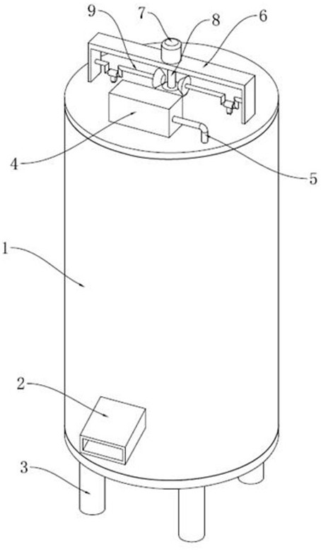
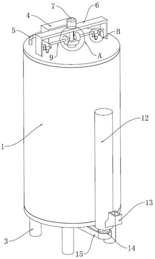
[0041] refer to Figure 1-12 , in an embodiment of the present invention, a quick drying device for organic fertilizers includes a drying box 1, a U-shaped frame 6 is installed on the top of the drying box 1, and a drying motor 7 is installed at the center of the upper end of the U-shaped frame 6. The output shaft 8 of the drying motor 7 is connected with a driving gear 11, and a driven gear 10 is meshed on both sides of the driving gear 11, and the outer center of the driven gear 10 is connected with a rotating shaft 9, and the rotating shaft 9 is provided with a rotating crank 17. The crank 17 is covered with a rotating curved sleeve 18, and a traction connecting rod 19 is installed on the rotating curved sleeve 18. The end of the traction connecting rod 19 away from the rotating curved sleeve 18 is hinged with a lifting connecting rod 20; specifically, the drying motor 7 is rotating At the same time, the output shaft 8 drives the driving gear 11 to rotate, and then meshes w...

Embodiment 2

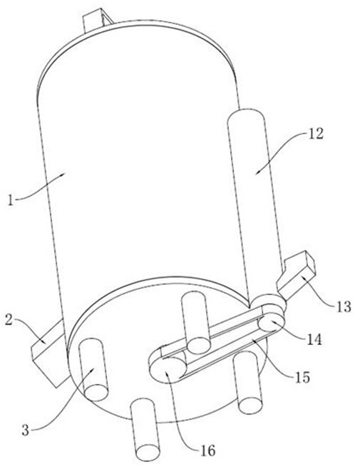
[0052] In another embodiment of the present invention, the difference between this embodiment and the above-mentioned embodiment is that, the bottom of the discharge plate 29 is connected to the bottom center of the drying box 1 through a limit post 31. Limiting cylinder 30, the bottom of limiting cylinder 30 is connected with driving pulley 16, and driving pulley 16 is connected with driven pulley 14 by belt 15, and driven pulley 14 upper end is connected with lifting shaft 34, and lifting shaft 34 wears A number of lifting screws 35 are connected to the lifting cylinder 12 fixed on the outer wall of the drying box 1, the top of the lifting cylinder 12 communicates with the inside of the drying box 1, and the bottom of the lifting cylinder 12 is also equipped with a feed hopper 13, specifically Yes, using the cooperation between the limit column 31 and the limit cylinder 30, the limit cylinder 30 is rotated, and finally under the action between the driving pulley 16, the belt ...


PUM


Abstract

The invention relates to the technical field of drying equipment, and discloses an organic fertilizer rapid drying device which comprises a drying box. A U-shaped frame is installed at the top of the drying box, a drying motor is installed in the center position of the upper end of the U-shaped frame, an output shaft of the drying motor is connected with a driving gear, the two sides of the driving gear are engaged with driven gears, a driving shaft is connected to the center position of the lower end of the driving gear, a drying shaft is connected to the bottom of the driving shaft through a flat key, an exhaust box is rotationally arranged at the upper side position of the drying shaft, the interior of the drying shaft is of a hollow structure, multiple drying holes communicating with the exhaust box are connected to the wall of the drying shaft in a penetrating manner, the exhaust box further communicates with an air suction box throw an air blowing pipe, the air suction box is fixed to the top end of the inner wall of the drying box, the air suction box is connected with a hot air box through an air inlet pipe, and the hot air box is fixed to the outer side of the top end of the drying box. According to the organic fertilizer rapid drying device, the drying shaft can rotate while moving up and down, organic fertilizer in the drying box can be effectively scattered, and the caking and stacking phenomena of the organic fertilizer are avoided.

Description

technical field [0001] The invention relates to the technical field of drying equipment, in particular to a quick drying device for organic fertilizers. Background technique [0002] Bio-organic fertilizer refers to a type of microbial fertilizer and organic fertilizer that is composed of specific functional microorganisms and organic materials that are mainly sourced from animal and plant residues (such as livestock and poultry manure, crop straw, etc.) and have been harmlessly treated and decomposed. Fertilizer with fertilizer effect. [0003] Organic fertilizer raw materials need to be dried before or after processing to improve the quality of organic fertilizer production and processing. However, the existing drying equipment is rough and simple, and the drying effect is average, and it is easy to be blocked by accumulated clumps of fertilizer during drying. , part of the organic fertilizer is still wet, which affects the subsequent processing quality, therefore, it nee...

Claims


Application Information

Patent Timeline
Patent Type & Authority Applications(China)
IPC IPC(8): F26B11/12F26B21/00F26B25/00F26B25/04
CPCF26B11/12F26B21/001F26B21/004F26B25/002F26B25/04F26B2200/12
Inventor 张焕刚林志红王秀波杨建闻李杨
Owner SHANGDONG TENOV PESTICIDES
Why Eureka
Try Eureka