Sludge separation device

A separation device and sludge technology, applied in separation methods, filtration separation, sludge treatment and other directions, can solve the problems of inability to separate sludge, sludge impurities and sewage, waste of filtration time, etc., so as to save separation time and avoid pollution. Mixing materials to ensure the effect of permeability

Active Publication Date: 2021-10-01
杭州国泰环保科技股份有限公司
View PDF13 Cites 1 Cited by
  • Summary
  • Abstract
  • Description
  • Claims
  • Application Information

AI Technical Summary

Problems solved by technology

[0005] In order to make up for the deficiencies of the existing technology, solve the problem that for some municipal sludge, the sludge not only contains sewage, but also has some small domestic garbage. The existing separation of sludge is only to separate sludge and sewage. The solid impurities need to be filtered again separately, and the sludge, sludge impurities and sewage cannot be separated at one time, which wastes the filtration time. A sludge separation device proposed by the present invention

Method used


Image

  • Sludge separation device
  • Sludge separation device
  • Sludge separation device

Examples


Embodiment 1

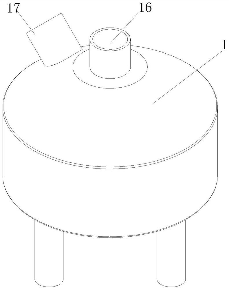
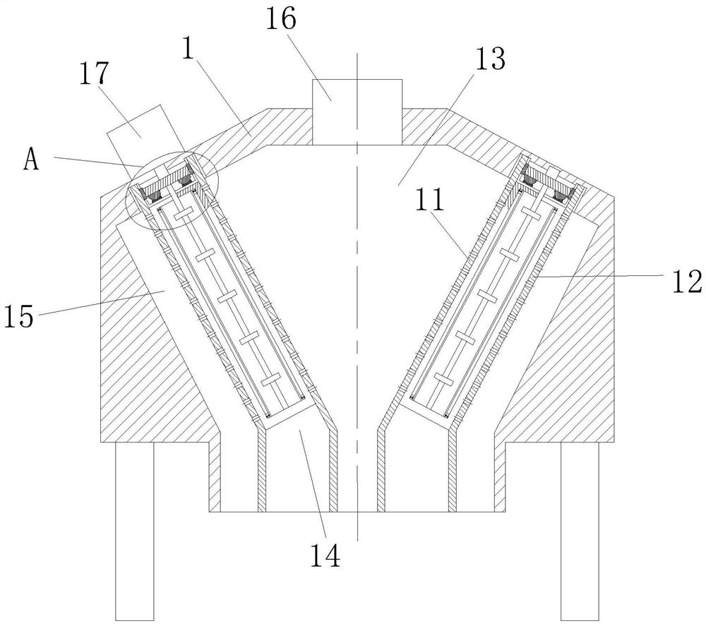
[0030] Such as Figure 1 to Figure 5 As shown, a sludge separation device according to the present invention includes a separation box 1; a feed inlet 16 is provided at the center of the top of the separation box 1; a first annular groove is provided on the inner wall of the slope at the top of the separation box 1 And the second annular groove, and the first annular groove is close to the center line of the separation box 1; the first filter plate 11 is rotatably connected in the first annular groove; the second filter plate 12 is rotatably connected in the second annular groove; The cross-section of the first filter plate 11 and the second filter plate 12 is an inverted cone; the inner diameter of the filter hole of the second filter plate 12 is less than the inner diameter of the filter hole of the first filter plate 11; the first filter plate 11 and A miscellaneous chamber 13 is formed at the center of the separation box 1, and the feed port 16 and the miscellaneous chambe...

Embodiment 2

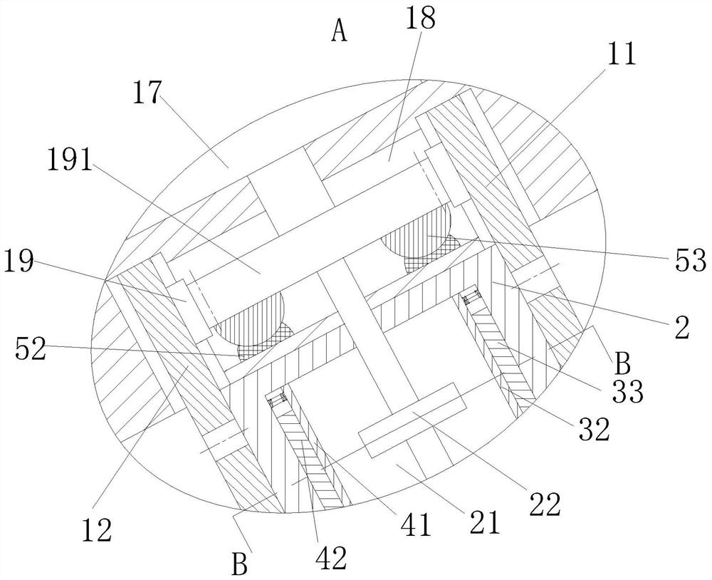
[0040] see Image 6 As shown in Comparative Example 1, as another embodiment of the present invention, a third annular groove 7 is provided on the outer wall of the cam 22; a set of cutting blades 71 is fixedly attached to the bottom of the third annular groove 7, And the cutting piece 71 is triangular; when working, because after the moisture in the sludge decreases, the viscosity of the sludge increases, which will affect the rotation of the cam 22 in the mud discharge chamber 14, and then affect the energy consumption of the motor 17, so A cutting piece 71 is arranged inside the cam 22. The cutting piece 71 can not only reduce the influence of the external sludge on the rotation of the cam 22, but also pulverize some solid particles in the sludge, and prevent the sludge from solidifying, which affects the quality of the sludge. Discharge.

[0041] Working principle: Put the municipal sludge into the separation box 1 through the feed port 16. At this time, the outlets of th...


PUM


Abstract

The invention belongs to the technical field of sludge separation, and particularly relates to a sludge separation device. The device comprises a separation box; a feeding hole is formed in the center of the top of the separation box; a first annular groove and a second annular groove are formed in the inner wall of the inclined surface of the top end of the separation box; the first annular groove is close to the center line of the separation box; a first filter plate is rotationally connected into the first annular groove; a second filter plate is rotationally connected into the second annular groove; and the sections of the first filter plate and the second filter plate are inverted cone-shaped. The invention provides the sludge separation device to solve the problems that for some municipal sludge which contains sewage and even contains some small-size household garbage, only the sludge and the sewage are separated in the existing sludge separation, solid impurities of the sludge need to be independently filtered again, sludge, sludge impurities and sewage cannot be separated at one time, and the filtering time is wasted.

Description

technical field [0001] The invention belongs to the technical field of sludge separation, in particular to a sludge separation device. Background technique [0002] The treatment of municipal municipal sludge needs to go through processes such as separation of impurities, dehydration and collection, and then the treated sludge can be reused, such as making building materials and fertilizers. [0003] There are also some technical solutions on sludge separation technology in the prior art. For example, a Chinese patent with application number 2019223097508 discloses a sludge impurity separation device, including a box body, and a sludge delivery pipe is sleeved on the top of the box body. , There are slide grooves on both sides of the box, sliding blocks are placed in the slide grooves, the first fixing block is welded on one end of the sliding block, and the first filter is installed between the two first fixing blocks through screws. The two sides of the box are welded wit...

Claims


Application Information

Patent Timeline
Patent Type & Authority Applications(China)
IPC IPC(8): B01D33/35B01D33/37B01D33/46B01D33/50B01D33/54B01D33/68B01D33/29C02F11/121C02F11/127
CPCB01D33/35B01D33/37B01D33/466B01D33/461B01D33/50B01D33/54B01D33/68B01D33/29C02F11/121C02F11/127Y02A40/20
Inventor 何小瑜夏玉坤彭贤辉赵江舟洪根惠沈飞凯金喆浩
Owner 杭州国泰环保科技股份有限公司
Why Eureka
Try Eureka