Monolateral cavity freestyle foaming mould

A foaming mold, unilateral technology, applied in the field of unilateral cavity free foaming mold, can solve the problems of substandard mechanical properties of products, affecting the cushioning performance of products, insufficient foaming of products, etc., and solve the problem of high market price , good practical effect, fast drying effect

Active Publication Date: 2017-01-25
SHANDONG UNIV
View PDF2 Cites 4 Cited by
  • Summary
  • Abstract
  • Description
  • Claims
  • Application Information

AI Technical Summary

Problems solved by technology

In traditional thermoforming molds, the slurry is placed in the entire cavity and is in contact with the upper and lower mold surfaces. The foaming of the prepared product is insufficient and the cell structure i

Method used


Image

  • Monolateral cavity freestyle foaming mould
  • Monolateral cavity freestyle foaming mould
  • Monolateral cavity freestyle foaming mould

Examples


Embodiment 1

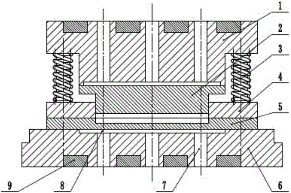
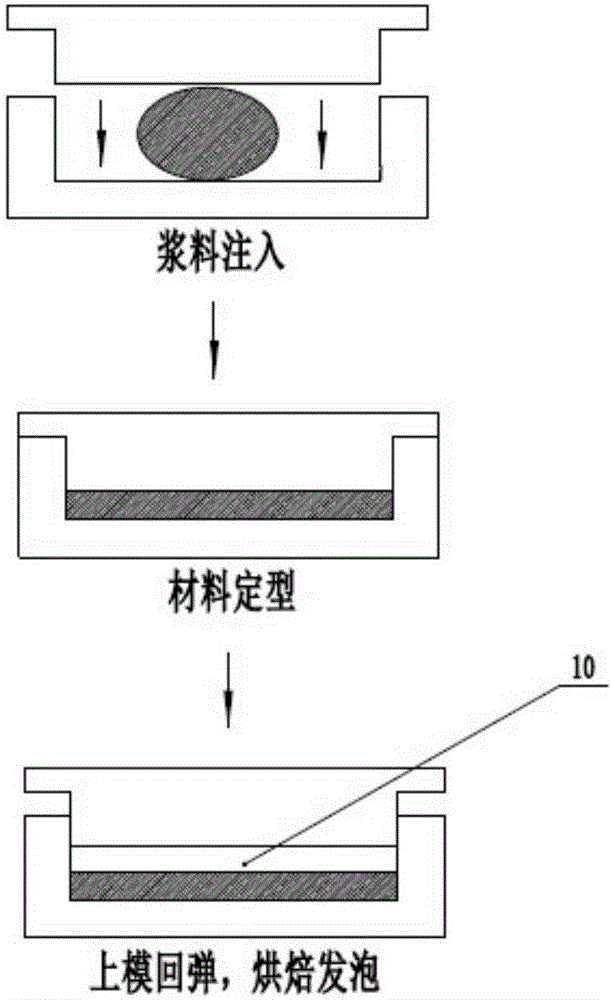
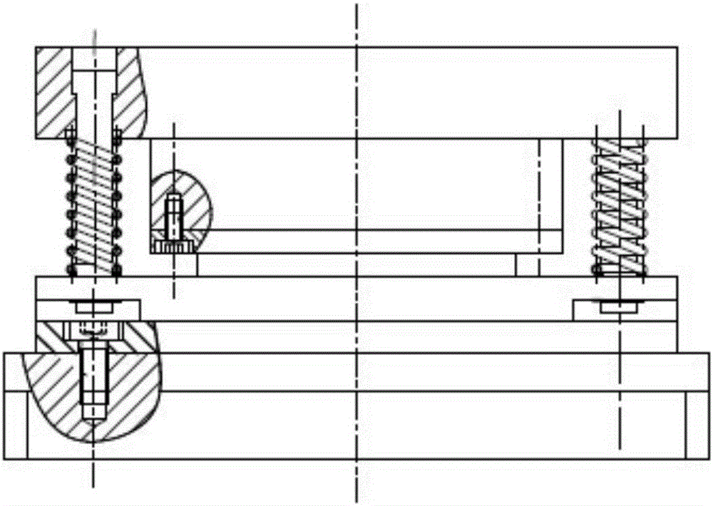
[0036] like Figure 1-2 As shown, the unilateral cavity free-form foaming mold includes aluminum alloy upper base 1, breathable steel upper mold 2, spring 3, aluminum alloy baffle 4, breathable steel lower mold 5, aluminum alloy lower base 6, row The air hole 7, the base sinking groove 8, the electric heating plate 9 and the unilateral foaming cavity 10, the breathable steel upper mold 2 and the breathable steel lower mold 5 are combined to form the cavity of the mold, the aluminum alloy upper base 1 and the aluminum alloy A spring 3 is arranged between the alloy baffles 4, such as image 3 As shown, the spring 3 is fixed on the lower surface of the upper base 1 of the aluminum alloy. After the upper and lower molds of the breathable steel are completed to mold the biomass material products, the upper and lower molds of the breathable steel rise a certain distance under the action of the resilience of the spring 3, so that the product is A unilateral foaming cavity 10 is form...

Embodiment 2

[0046] The single-sided cavity free-form foaming mold includes an upper mold and a lower mold. The surface of the lower mold is provided with a groove for placing biomass materials. Part of the upper mold can be embedded in the groove. The other side moves relatively to extrude the biomass material, so that the biomass material is formed in the groove, the upper die and the lower die are respectively connected with the moving mechanism, and the moving mechanism acts after the upper die and the lower die extrude the biomass material for a set time. The lower and upper molds are separated from the lower mold; in this solution, the upper mold or the lower mold can move relative to each other, which improves the separation rate of the two, and the moving mechanism can be an electric cylinder or other power devices.


PUM


Abstract

The invention discloses a monolateral cavity freestyle foaming mould, which comprises an upper mould and a lower mould, wherein a groove for storing a biologic material is arranged in the surface of the lower mould; the upper mould can be partially embedded into the groove; one of the upper mould or the lower mould can move relative to the other one so as to extrude the biologic material, so that the biologic material is formed in the groove; one of the upper mould or the lower mould is connected with a moving mechanism; the upper mould is separated from the groove under the action of the moving mechanism after the setting time of extruding the biologic material by the upper mould and the lower mould, and the biologic material is foamed freely. According to the monolateral cavity freestyle foaming mould, the product drying time is greatly reduced, the original slurry dosage of the product is reduced, the product bubble quality is improved, the buffer performance is improved, meanwhile, the material raw material use cost and the product manufacturing production cost are reduced, and the monolateral cavity freestyle foaming mould has a favorable actual effect, and has a favorable reference significance on mould production at present.

Description

technical field [0001] The invention relates to the field of molds, in particular to a free-form foaming mold with unilateral cavity. Background technique [0002] With the rise of the logistics industry, the market has put forward a huge demand for packaging products. While plastic packaging products provide convenience for human life, the products are not degradable, which brings serious harm to the environment. The degradable advantage of the product has become a substitute for cushioning plastic packaging products such as EPE and EPS. [0003] Unlike plastic foam, which is foamed in the material filling process, the existing foamed biomass materials are produced by traditional hot-pressing molds. In traditional hot-pressing molds, the slurry is placed in the entire cavity and is in contact with the surfaces of the upper and lower molds. The prepared products have insufficient foaming and uneven cell structure, which seriously affects the cushioning performance of the p...

Claims


Application Information

Patent Timeline
IPC IPC(8): B29C44/58B29C44/02
CPCB29C44/027B29C44/585B29C44/588
Inventor 李方义张传伟徐婕谢麒金宗学陈帅王黎明李燕乐李剑峰郭安福
Owner SHANDONG UNIV
Why Eureka
Try Eureka