Efficient oil-water separation device for chemical engineering

An oil-water separation device, high-efficiency technology, applied in the direction of liquid separation, separation method, grease/oily substance/floating matter removal device, etc., can solve the problems of environmental damage, waste of resources, etc., to speed up the separation rate, facilitate processing and utilization Effect

Inactive Publication Date: 2018-11-06
FOSHAN KEFENG CULTURE COMM CO LTD
View PDF7 Cites 4 Cited by
  • Summary
  • Abstract
  • Description
  • Claims
  • Application Information

AI Technical Summary

Problems solved by technology

[0003] The purpose of the present invention is to provide a high-efficiency oil-water separation device for chemical industry, the rotating disc and the separation housing, the motor can drive the rotating disc to rotate, thereby driving the separation housing on the surface of the rotating disc to rotate, and the oil-water mixed liquid in the separation housing is subjected to centrifugal force Due to the difference in the density of oil and water, the oil moves to the top of the mixed liquid during th

Method used


Image

  • Efficient oil-water separation device for chemical engineering
  • Efficient oil-water separation device for chemical engineering
  • Efficient oil-water separation device for chemical engineering

Examples


Embodiment 1

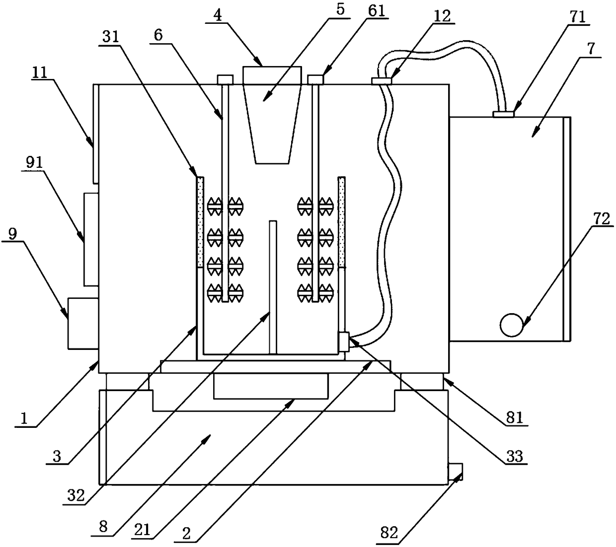
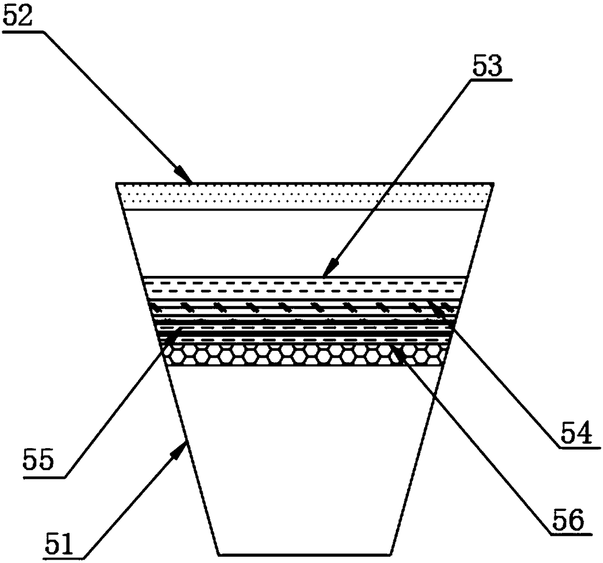
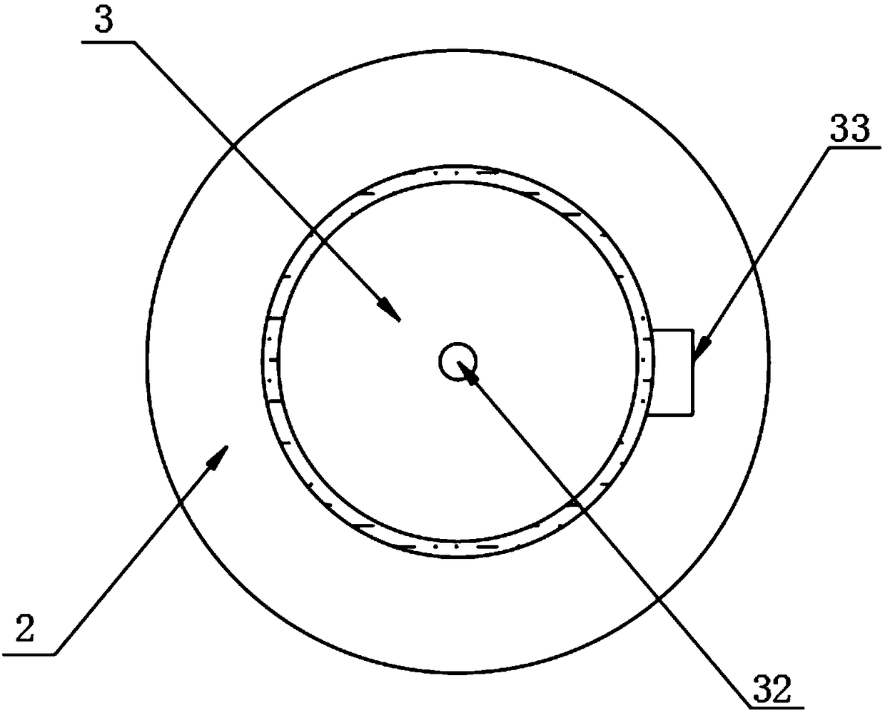
[0022] The present invention provides such as Figure 1-3 The shown high-efficiency oil-water separation device for chemical industry comprises a device casing 1, a rotating disk 2 is arranged at the bottom of the inner wall of the device casing 1, a motor 21 is arranged at the bottom of the rotating disk 2, and the rotating disk 2 is connected to the motor. 21 Transmission connection, the top of the rotating disk 2 is fixed with a separation shell 3, the top of the device shell 1 is provided with a feeding port 4, and the bottom of the feeding port 4 is connected with a filter device 5, and the filter device 5 It includes a filter housing 51, an inner thread 52, a filter screen 53, a filter element 54, an activated carbon adsorption layer 55 and a filter bag filling layer 56. The filter device 5 is provided with a rotating shaft 6 on both sides. A water storage chamber 7 is provided on one side, an oil storage chamber 8 is provided at the bottom of the device housing 1 , and ...

Embodiment 2

[0026] The filter housing 51 is arranged on the top of the inner wall of the device housing 1, and the top of the inner wall of the filter housing 51 is provided with an inner thread 52, and the inner thread 52 is threadedly connected with the feeding port 4. There is a filter screen 53, the bottom of the filter screen 53 is provided with a filter element 54, the bottom of the filter element 54 is provided with an activated carbon adsorption layer 55, and the bottom of the activated carbon adsorption layer 55 is provided with a filter bag filling layer 56, the filter bag is filled with The interior of the layer 56 is filled with nitrifying bacteria.

[0027] The top of the rotating shaft 6 is provided with a motor 61 , the motors 61 are arranged on both sides of the feeding port 4 , the rotating shaft 6 is connected with the motor 61 in a driving manner, and the rotating shaft 6 extends to the interior of the separation housing 3 and the rotating shaft 6 There is a stirring ro...


PUM


Abstract

The invention discloses an efficient oil-water separation device for chemical engineering. The efficient oil-water separation device comprises a device shell, wherein a rotating disk is arranged at the bottom of the inner wall of the device shell; a motor is arranged at the bottom of the rotating disk; the rotating disk is connected with the motor in a transmission manner; a separation shell is fixedly arranged at the top of the rotating disk; a material inlet is formed in the top of the device shell; a filter device is connected to the bottom of the material inlet; rotating shafts are arranged on two sides of the filter device; a water storage chamber is arranged on one side of the device shell. By the arrangement of the rotating disk and the separation shell, the motor works to drive therotating disk to rotate, so as to drive the separation shell on the surface of the rotating disk to rotate; oil-water mixed liquid in the separation shell slides on the inner wall of the separation shell under the action of centrifugal force; as oil and water have different densities, the oil moves to the top of the mixed liquid and the water moves to the bottom of the mixed liquid during rotation; the oil leaves the separation shell after passing through the filter plate, so that the quick separation work of the oil-water mixed liquid is completed.

Description

technical field [0001] The invention relates to the field of chemical equipment, in particular to a high-efficiency oil-water separation device for chemical industry. Background technique [0002] In chemical production, wastes of oil-water mixed liquids are often generated, which will damage the environment after being directly discharged. At the same time, the oil in the oil-water mixed liquids can also be recycled for reuse, which directly wastes resources. Therefore, a chemical industry was invented. It is necessary to solve the above problems with a high-efficiency oil-water separation device. SUMMARY OF THE INVENTION [0003] The purpose of the present invention is to provide a high-efficiency oil-water separation device for chemical industry, a rotating disk and a separation shell, the motor can drive the rotating disk to rotate, thereby driving the separation shell on the surface of the rotating disk to rotate, and the oil-water mixed liquid in the separation shell...

Claims


Application Information

Patent Timeline
IPC IPC(8): B01D17/022B01D17/02B01D17/12C02F1/40
CPCB01D17/0202B01D17/10B01D17/12C02F1/40
Inventor 薛军
Owner FOSHAN KEFENG CULTURE COMM CO LTD
Why Eureka
Try Eureka