Forward flow control work multi-way valve structure

A technology of flow control and multi-way valve, which is applied in the direction of fluid pressure actuators, servo motor components, mechanical equipment, etc., can solve the problems of complex structure, inability to meet the requirements of complex composite actions, high cost, etc., and achieve flexible and satisfying distribution modes. The effect of complex compound movement requirements

Active Publication Date: 2017-12-22
XIAN FLIGHT SELF CONTROL INST OF AVIC
View PDF5 Cites 1 Cited by
  • Summary
  • Abstract
  • Description
  • Claims
  • Application Information

AI Technical Summary

Problems solved by technology

The traditional construction machinery flow control scheme has complex structure and high cost, and the fixed flow distribution mode cannot meet the requirements of complex compound actions

Method used


Image

  • Forward flow control work multi-way valve structure
  • Forward flow control work multi-way valve structure

Examples


Embodiment Construction

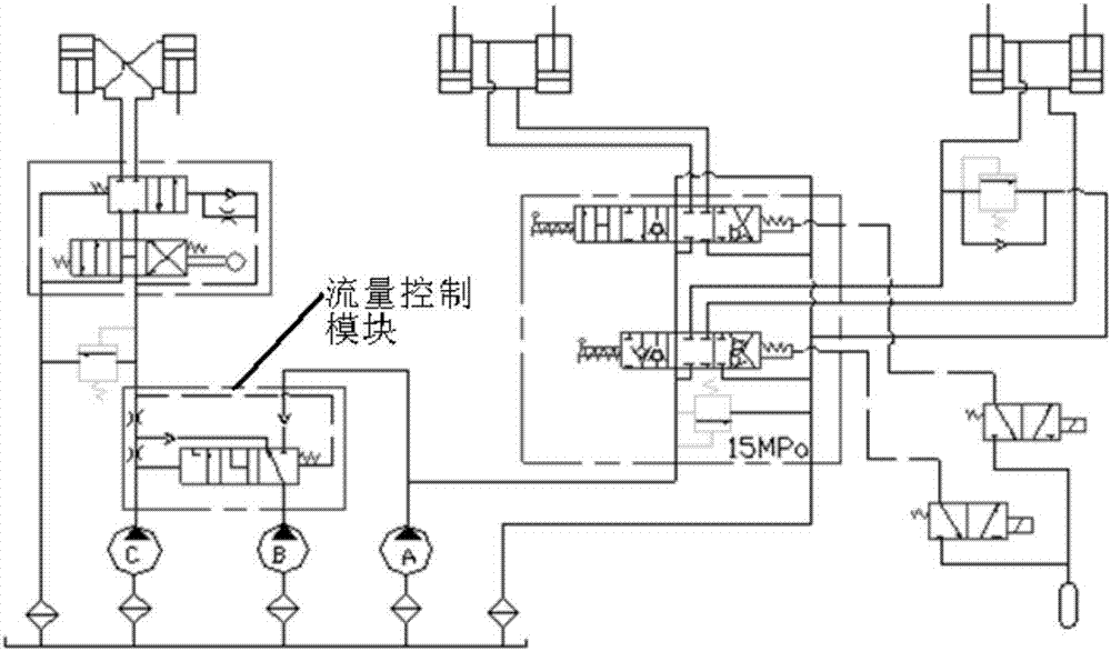
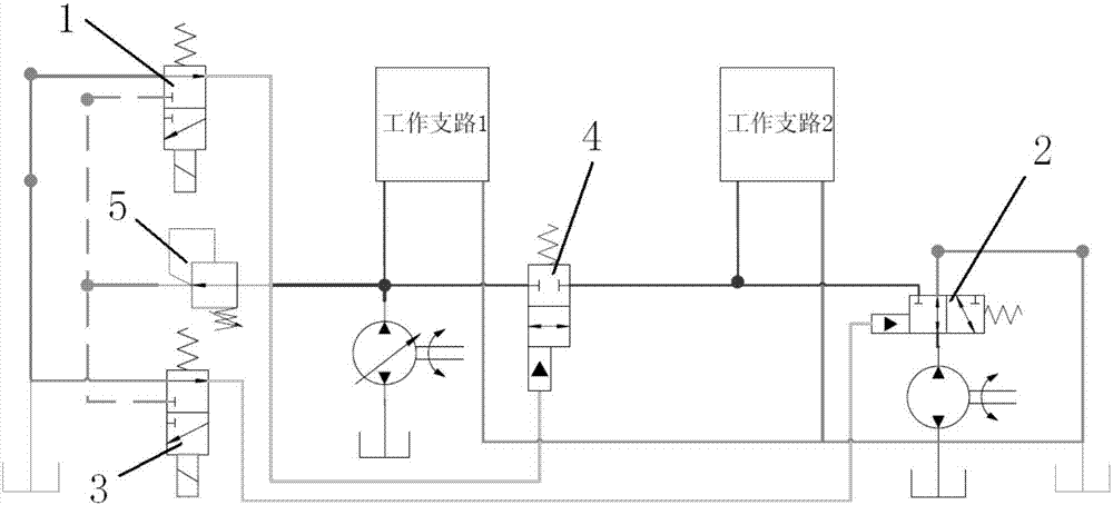
[0019] A multi-way valve structure with positive flow control, including proportional solenoid valve A1, unloading valve 2, proportional solenoid valve B3, confluence valve 4, pressure reducing valve 5, wherein proportional solenoid valve A(1) and proportional solenoid valve B(3) adopts 24V DC power supply, and controls the current of the solenoid valve in the range of 0-700mA through PWM, so as to proportionally control the output pressure of the control chamber of the solenoid valve. The pilot oil inlet and outlet of pressure reducing valve 5 are connected to the oil inlet and outlet of proportional solenoid valve A1, the control chamber of proportional solenoid valve A1 is connected to the control chamber of unloading valve 2 spool, and the oil inlet and outlet of unloading valve 2 are connected to the oil inlet and outlet of variable pump respectively. It is connected with the total oil return; the pilot oil inlet and outlet of the pressure reducing valve 5 are connected wi...


PUM


Abstract

The invention discloses a forward flow control work multi-way valve structure. The forward flow control work multi-way valve structure is characterized by comprising a proportional electromagnetic valve A (1), an unloading valve (2), a proportional electromagnetic valve B (3), a confluence valve (4) and a pressure reducing valve (5). Pilot inlet and return oil is connected with inlet and return oil of the proportional electromagnetic valve A (1). A control cavity of the proportional electromagnetic valve A (1) is connected with a valve element control cavity of the unloading valve (2). Inlet and return oil of the unloading valve (2) is connected with inlet oil and main return oil of a variable pump. Pilot inlet and return oil of the pressure reducing valve (5) is connected with inlet and return oil of the proportional electromagnetic valve B (3). A control cavity of the proportional electromagnetic valve B (3) is connected with a valve element control cavity of the confluence valve (4). Inlet and return oil of the confluence valve (4) is connected with inlet oil and main return oil of a metering pump. By means of the forward flow control work multi-way valve structure, flow distribution of a branch way can be controlled by controlling power supply currents of the electromagnetic valves, and accurate flow distribution control is achieved.

Description

1. Technical field [0001] The invention belongs to the design of a novel hydraulic structure in the field of construction machinery, and in particular relates to a hydraulic structure replacing traditional flow control. 2. Background technology [0002] The flow control of traditional construction machinery realizes flow control through flow control valves, check valves and throttle valves, provides flow for different working modules and coordinates flow priority among them ( figure 1 is a typical loader hydraulic schematic). The traditional construction machinery flow control scheme has complex structure and high cost, and the fixed flow distribution mode cannot meet the requirements of complex compound actions. [0003] This patent proposes a new structural scheme to replace the original flow distribution structural scheme. By controlling the solenoid valve, the control of the slide valve is realized, and then the flow distribution is realized. The new scheme has the adv...

Claims


Application Information

Patent Timeline
Patent Type & Authority Applications(China)
IPC IPC(8): F15B13/02
Inventor 行登海花韬夏立群田一松
Owner XIAN FLIGHT SELF CONTROL INST OF AVIC
Why Eureka
Try Eureka