Supercharge Your Innovation With Domain-Expert AI Agents!

Array waveguide grating of reducing kerf additional optical loss and method for reducing kerf additional optical loss of array waveguide grating

An arrayed waveguide grating and additional light technology, which is applied in the direction of optical waveguide and light guide, can solve the problems of device failure, affecting the spectral characteristics of the entire arrayed waveguide grating device, and increasing additional loss of the slitting process, so as to achieve low and reduced additional light loss. Process difficulty and the effect of improving yield

Active Publication Date: 2017-12-22
GUANGXUN SCI & TECH WUHAN
View PDF9 Cites 1 Cited by
  • Summary
  • Abstract
  • Description
  • Claims
  • Application Information

AI Technical Summary

Problems solved by technology

If the slicing environment or slit depth is not well controlled, the additional loss of the slit process will increase; if edge chipping occurs during the slit process, it will directly affect the spectral characteristics of the entire arrayed waveguide grating device, resulting in device failure

Method used


Image

  • Array waveguide grating of reducing kerf additional optical loss and method for reducing kerf additional optical loss of array waveguide grating
  • Array waveguide grating of reducing kerf additional optical loss and method for reducing kerf additional optical loss of array waveguide grating
  • Array waveguide grating of reducing kerf additional optical loss and method for reducing kerf additional optical loss of array waveguide grating

Examples


Embodiment Construction

[0030] The following will clearly and completely describe the technical solutions in the embodiments of the present invention with reference to the accompanying drawings in the embodiments of the present invention. Obviously, the described embodiments are only some, not all, embodiments of the present invention. Based on the embodiments of the present invention, all other embodiments obtained by persons of ordinary skill in the art without making creative efforts belong to the protection scope of the present invention.

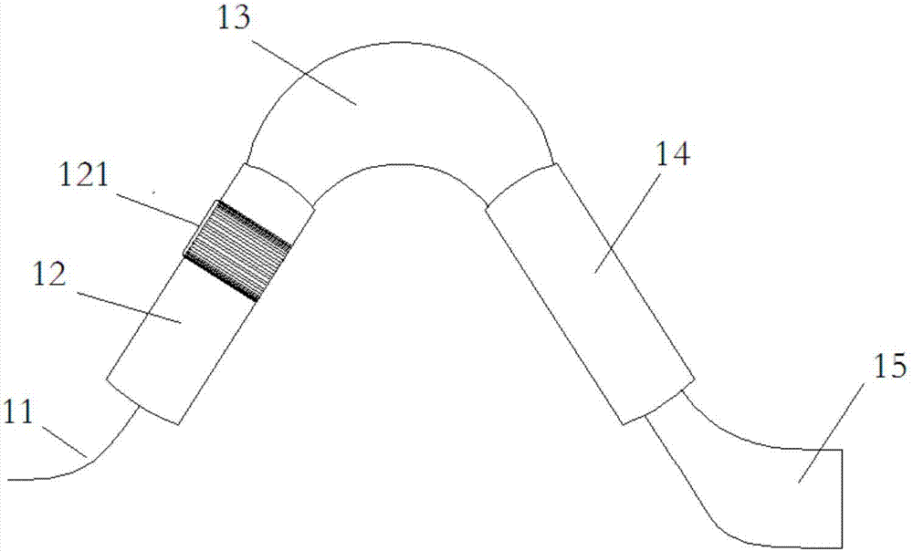
[0031] The embodiment of the present invention discloses an arrayed waveguide grating that reduces the additional optical loss of the slit, such as figure 1 As shown, at least one input waveguide 11 , at least one input slab region 12 , at least one arrayed waveguide region 13 , at least one output slab region 14 , and at least one output waveguide 15 are included. in:

[0032] There is a period segmented waveguide area 121 on the input slab area 12 .

[003...


PUM


Abstract

The present invention relates to a grating and a method, belongs to the optical communication technology field, and especially relates to an array waveguide grating of reducing kerf additional optical loss and a method for reducing kerf additional optical loss of an array waveguide grating. The array waveguide grating comprises an input waveguide, an input flat area, an array waveguide, an output flat area and an output waveguide; and the flat areas have period sectional-type waveguide areas. The speckle sizes of light wave is changed from small to big and then from big to small when the light performs propagation in the period sectional-type waveguide areas, the kerf is formed on the period sectional-type waveguide areas on the flat areas, and the additional optical loss generated by the kerf is low to reduce the requirement for the kerf width, reduce the kerf technology difficulty and improve the kerf yield.

Description

technical field [0001] The invention relates to a grating and a method, belonging to the technical field of optical communication, in particular to an arrayed waveguide grating and a method for reducing the additional optical loss of slits. Background technique [0002] The miniaturization and low cost of optical devices is the development trend of the industry. The material refractive index contrast of the commercialized planar light waveguide (PLC) technology platform has been continuously improved, from 0.45% to 0.75%, and then increased to the current 1.5-2%. The waveguide’s ability to constrain light waves has become stronger. The cross-sectional dimensions of the waveguides have become smaller, and the minimum bend radius has been reduced, so the size of the device has also continued to decrease. [0003] However, the increased refractive index contrast results in a smaller mode field in the optical waveguide, which diverges at a larger angle when light travels from t...

Claims


Application Information

Patent Timeline
IPC IPC(8): G02B6/12
Inventor 张冀马卫东凌九红吴凡胡家艳
Owner GUANGXUN SCI & TECH WUHAN
Features
  • R&D
  • Intellectual Property
  • Life Sciences
  • Materials
  • Tech Scout
  • Unparalleled Data Quality
  • Higher Quality Content
  • 60% Fewer Hallucinations
Learn More