
Design method of magnetically coupled resonance high-efficiency power transmission coil

A magnetic coupling resonance, power transmission technology, applied in circuits, inductors, electrical components and other directions, can solve the problems of complex antenna alignment technology, complex system, large microwave energy loss, etc., to suppress frequency splitting phenomenon, improve transmission efficiency , to maintain the effect of high-efficiency transmission

Active Publication Date: 2020-05-08
HENAN NORMAL UNIV
View PDF1 Cites 0 Cited by
  • Summary
  • Abstract
  • Description
  • Claims
  • Application Information

AI Technical Summary

Problems solved by technology

[0004] The second type is the microwave type, which transmits and receives electromagnetic energy through the antenna, which has the advantages of long transmission distance and high transmission power, but in the process of energy transmission, more complicated antenna alignment technology is required, and the microwave energy loss is large and the efficiency is high. Low, has serious harm to the human body, and is generally used in special occasions;
However, these additional circuits complicate the system and consume additional power

Method used


Image

  • Design method of magnetically coupled resonance high-efficiency power transmission coil
  • Design method of magnetically coupled resonance high-efficiency power transmission coil
  • Design method of magnetically coupled resonance high-efficiency power transmission coil

Examples


Embodiment

[0043] A design method for magnetically coupled resonance high-efficiency power transmission coils, which is realized by the following steps:

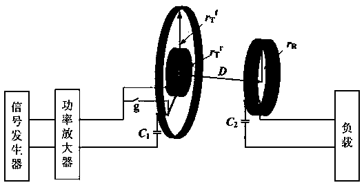
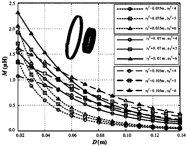
[0044] Step 1. For short-distance transmission, the transmitting end of the WPT / MRC system is a forward and reverse series coil, that is, the forward and reverse series coil is used as the transmitting coil, and the receiving end is a one-way coil, that is, the one-way coil is used as the receiving coil; The coil is composed of a forward coil and a reverse coil, the forward coil is outside, and the reverse coil is embedded inside the forward coil, and the current flowing through the forward coil and the reverse coil is opposite; The directional coils are all helical circular coils; the forward and reverse series coils at the transmitting end and the unidirectional coil at the receiving end are coaxially placed, and the radius of the unidirectional coil at the receiving end is set to r R , the number of turns is n R , set the forward c...


PUM


Abstract

The invention discloses a magnetic coupling resonance high-efficiency power transmission coil design method, which belongs to the technical field of wireless power transmission devices. The method provided by the invention comprises the steps that the size of a unidirectional coil on a receiving end is determined according to a charging target, and the size of a forward coil and a reverse coil on a transmitting end is determined according to a power supply; the turns ratio between the forward coil and the reverse coil on the transmitting end is determined according to a mutual inductance formula; the number of turns of the reverse coil on the transmitting end is adjusted; an appropriate number of turns is selected according to the flatness of the curve of the mutual inductance between the forward and reverse series coils on the transmitting end and the unidirectional coil on the receiving end, wherein the curve of the mutual inductance changes with the transmission distance; and two adjustable capacitors C1 and C2 are used to tune the forward and reverse series coils on the transmitting end and the unidirectional coil on the receiving end at the operating frequency. According to the invention, for short-distance, the forward and reverse series coils are used as the transmitting coils of a WPT / MRC system to effectively suppress the generation of a frequency splitting phenomenon; for long-distance, the forward coil is used as the transmitting coil of the WPT / MRC system to maintain high-efficiency transmission of the system.

Description

technical field [0001] The invention belongs to the technical field of wireless power transmission equipment, and in particular relates to a design method of a magnetic coupling resonance high-efficiency power transmission coil. Background technique [0002] As a more flexible, convenient and safe energy transmission method, wireless power transmission has attracted widespread attention at home and abroad. So far, according to different energy transmission principles and distances, wireless energy transmission methods can be divided into three categories: [0003] The first type is electromagnetic induction, which is mainly used for wireless power supply of mobile devices. It is a safe, reliable and flexible power transmission technology, but its transmission distance is very short, about a few centimeters; [0004] The second type is the microwave type, which transmits and receives electromagnetic energy through the antenna, which has the advantages of long transmission di...

Claims


Application Information

Patent Timeline
Patent Type & Authority Patents(China)
IPC IPC(8): H02J50/12H01F38/14
CPCH01F38/14H02J50/12
Inventor 王萌施艳艳高伟康范悦
Owner HENAN NORMAL UNIV
Learn More