
Feeding unit in iron removal device

A technology of feeding and feeding plate, which is applied in the field of feeding unit, can solve the problems that iron parts cannot be adsorbed on the chain type iron remover, and the effect of iron removal is not obvious, so as to achieve the effect of easy filtering and increasing stroke

Inactive Publication Date: 2017-12-29
ZHENJIANG YUANDA TRANSMISSION MACHINERY
View PDF9 Cites 0 Cited by
  • Summary
  • Abstract
  • Description
  • Claims
  • Application Information

AI Technical Summary

Problems solved by technology

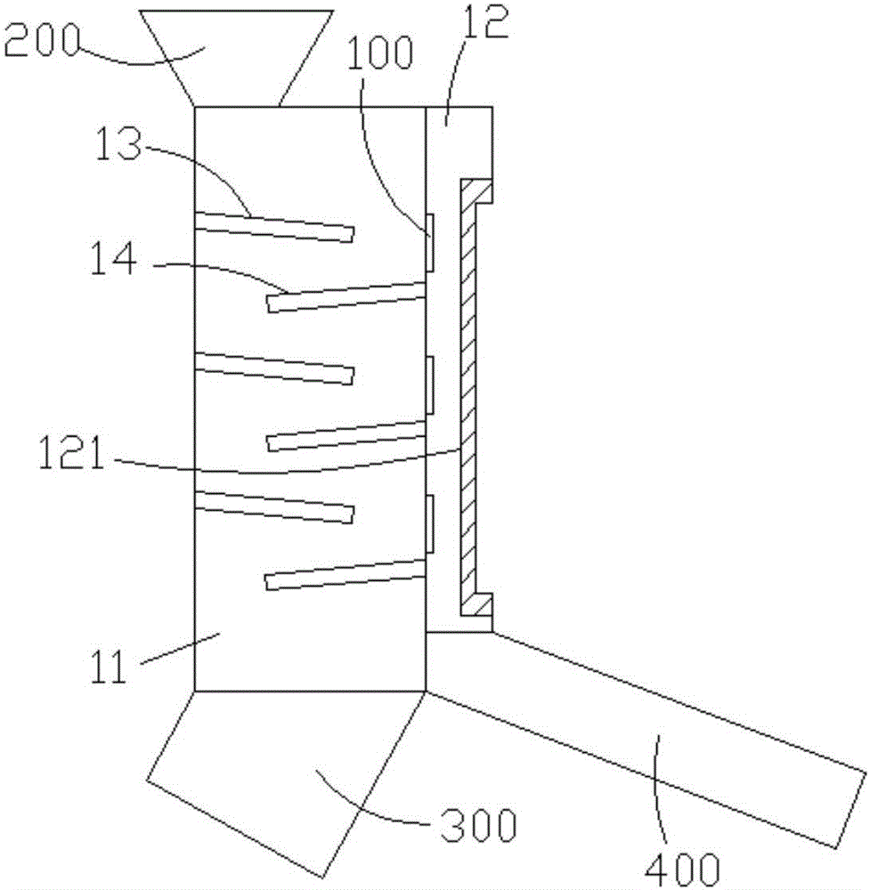
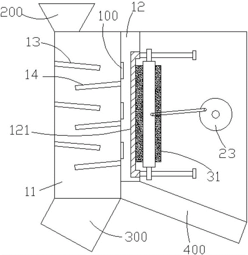
[0002] Some chain-type iron removers on the existing market can realize automatic removal of iron parts. When the chain-type iron remover is in use, it is placed above the material conveyor belt, and absorbs iron parts in the material during the material transportation process. This structure is in use At the same time, because the chain type iron remover and the material conveyor belt are moving at the same time, it will cause some iron parts to be unable to be adsorbed on the chain type iron remover, resulting in insignificant iron removal effect

Method used


Image

  • Feeding unit in iron removal device
  • Feeding unit in iron removal device

Examples


Embodiment Construction

[0012] The present invention will be further described below in conjunction with the accompanying drawings.

[0013] Such as figure 1 As shown, a feeding unit in a deironing device of the present invention includes a feeding housing 11, an unloading iron housing 12, a first feeding board 13 and a second feeding board 14, several first feeding boards 13 and several first feeding boards The two feeding plates 14 are layered and fixed downwards in the inner cavity of the feeding housing 11, and the first feeding plate 13 and the second feeding plate 14 are arranged alternately, on the side wall of the feeding housing 11 and located on each A taphole 100 is arranged above the second feeding plate 14 . The unloading shell 12 is fixed on the outer wall of the feeding shell 11 , and the inner chamber of the unloading shell 12 communicates with the taphole 100 .

[0014] In order to better protect the iron-discharging housing 12 and prevent iron pieces from scratching the iron-disch...


PUM


Abstract

The invention discloses a feeding unit in an iron removal device. The feeding unit comprises a feeding shell, an iron discharge shell, a plurality of first feeding plates and a plurality of second feeding plates. The first feeding plates and the second feeding plates are layered, are downwardly obliquely fixed into an inner cavity of the feeding shell and are staggered with one another, iron outlets are formed in a side wall of the feeding shell, and each iron outlet is particularly formed in a position above the corresponding second feeding plate; the iron discharge shell is fixed onto the outer wall of the feeding shell, and an inner cavity of the iron discharge shell is communicated with the iron outlets. The feeding unit has the advantages that material movement stroke can be increased by the first feeding plates and the second feeding plates, and accordingly iron can be conveniently sufficiently filtered out.

Description

Technical field: [0001] The invention relates to a feeding unit in an iron removal device. Background technique: [0002] Some chain-type iron removers on the existing market can realize the automatic removal of iron parts. When the chain-type iron remover is used, it is placed above the material conveyor belt, and absorbs iron parts in the material during the material conveying process. This structure is in use At this time, since the chain type iron remover and the material conveyor belt are moving at the same time, some iron parts cannot be adsorbed on the chain type iron remover, resulting in insignificant iron removal effect. Invention content: [0003] The present invention provides a feeding unit in an iron removal device in order to solve the above-mentioned problems in the prior art. [0004] The technical solutions adopted in the present invention include: a feeding unit in the iron removal device, including a feeding shell, an iron unloading shell, a first feed...

Claims


Application Information

Patent Timeline
IPC IPC(8): B03C1/02
CPCB03C1/02
Inventor 马料宝马俊马成
Owner ZHENJIANG YUANDA TRANSMISSION MACHINERY
Learn More