Supercharge Your Innovation With Domain-Expert AI Agents!

Weft yarn detection method and weft yarn detection device for air-jet loom

A technology of air-jet loom and detection method, which is applied in looms, weaving, textiles and papermaking, etc., and can solve problems such as failure to respond to the use of weft brakes, failure to issue effective warnings for weft sagging, etc.

Inactive Publication Date: 2019-11-22
TOYOTA IND CORP
View PDF10 Cites 0 Cited by
  • Summary
  • Abstract
  • Description
  • Claims
  • Application Information

AI Technical Summary

Problems solved by technology

[0008] Therefore, the standard deviation TWσ of the end arrival time TW cannot effectively warn against the generation of weft yarn sagging when using the weft yarn brake
In addition, the weft insertion status display device of the loom disclosed in Japanese Patent Application Laid-Open No. 2009-215694 does not deal with the use of the weft brake.

Method used


Image

  • Weft yarn detection method and weft yarn detection device for air-jet loom
  • Weft yarn detection method and weft yarn detection device for air-jet loom
  • Weft yarn detection method and weft yarn detection device for air-jet loom

Examples


Embodiment Construction

[0022] The following combination Figure 1 to Figure 6 c describes an embodiment that actualizes the present invention.

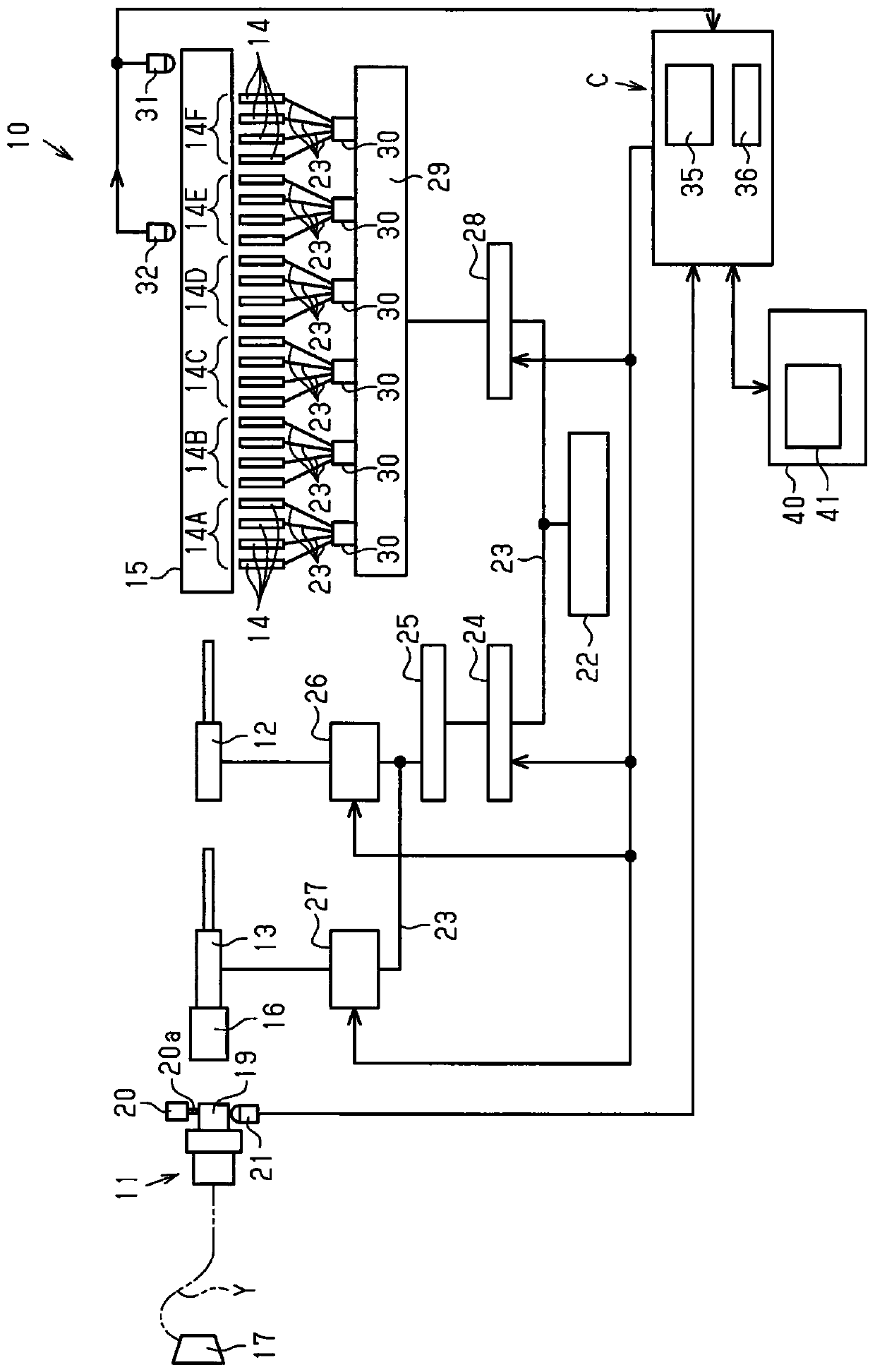
[0023] Such as figure 1 As shown, the weft inserting device 10 of the air-jet loom includes a weft accumulating device 11, a main nozzle 12, a serial nozzle 13 arranged on the upstream side of the main nozzle 12, and a plurality of sub-nozzles arranged on the downstream side of the main nozzle 12. Groups 14A-14F, reed 15. On the reed 15, a plurality of rows of reed teeth having guide recesses are arranged along the weft insertion direction. The tandem nozzle 13 is provided with a weft brake 16 . Each of the sub-nozzle groups 14A to 14F is composed of four sub-nozzles 14 .

[0024] The weft yarn accumulating device 11 winds and stores the weft yarn Y supplied from the weft yarn bobbin 17 serving as a yarn supplying section around a length measuring drum 19 . The weft accumulating device 11 has a locking pin 20 a that is driven by an electromagnetic sol...


PUM


Abstract

The invention provides a weft yarn detection method for an air jet loom and a weft yarn detection device. The weft yarn detection device is suitable for an air jet loom having a main nozzle, a sub nozzle and a weft brake and the weft yarns are inserted by the air jet from the main nozzle and the sub nozzle. The weft yarn detection device has a sensor disposed before the position where the weft tip reaches the brake timing of the weft brake, a calculating mean for calculating the standard deviation of the intermediate arrival timing of the weft tip detected by the sensor, and a warning output unit (warning / stop display unit) that issues a warning when the standard deviation calculated by the calculation unit exceeds the threshold value.

Description

technical field [0001] The present invention relates to a weft detection method and a weft detection device for an air-jet loom, and more particularly, to a weft detection method and a weft detection device for an air-jet loom equipped with a weft brake that brakes the weft when the weft is in flight. Background technique [0002] When using an air-jet loom to weave high-quality fabrics, it is very important to make the weft yarn reach the specified weft insertion end position at the specified time. Therefore, conventionally, a weft insertion status display device for a loom that can easily grasp a time-series change in a weft flight status has been proposed. For example, the device disclosed in Japanese Patent Application Laid-Open No. 2009-215694 is equipped with a weft finder at a position opposite to the weft flight path near the weaving end portion on the side opposite to weft insertion. The weft feeler has sensors at positions that can be reached by normally picked we...

Claims


Application Information

Patent Timeline
Patent Type & Authority Patents(China)
IPC IPC(8): D03D51/34
CPCD03D51/34D03D47/3073D03D47/3093
Inventor 牧野洋一荒井隆二
Owner TOYOTA IND CORP
Features
  • R&D
  • Intellectual Property
  • Life Sciences
  • Materials
  • Tech Scout
  • Unparalleled Data Quality
  • Higher Quality Content
  • 60% Fewer Hallucinations
Learn More