
Weft insertion device of air-jet loom

A weft insertion device and air-jet loom technology, which is applied in looms, textiles, textiles and papermaking, etc., can solve problems such as excessive air consumption, inability to achieve high-speed weft insertion, and large distance between auxiliary nozzles and reeds

Active Publication Date: 2011-06-08
TOYOTA IND CORP
View PDF6 Cites 9 Cited by
  • Summary
  • Abstract
  • Description
  • Claims
  • Application Information

AI Technical Summary

Problems solved by technology

When this method of the second reference is applied to the weft insertion device of the first reference, although the reed teeth in the second area of ​​the weft insertion path for stabilizing the flight position of the weft yarn, especially in the second area of ​​the weft insertion path In the first half of the first half, the inclination angle of the wall surface of the guide recess increases, but the desired high-speed weft insertion cannot be achieved due to the large distance between the sub-nozzle and the reed
Alternatively, more air consumption is required to achieve the desired high-speed weft insertion

Method used


Image

  • Weft insertion device of air-jet loom
  • Weft insertion device of air-jet loom
  • Weft insertion device of air-jet loom

Examples


Embodiment Construction

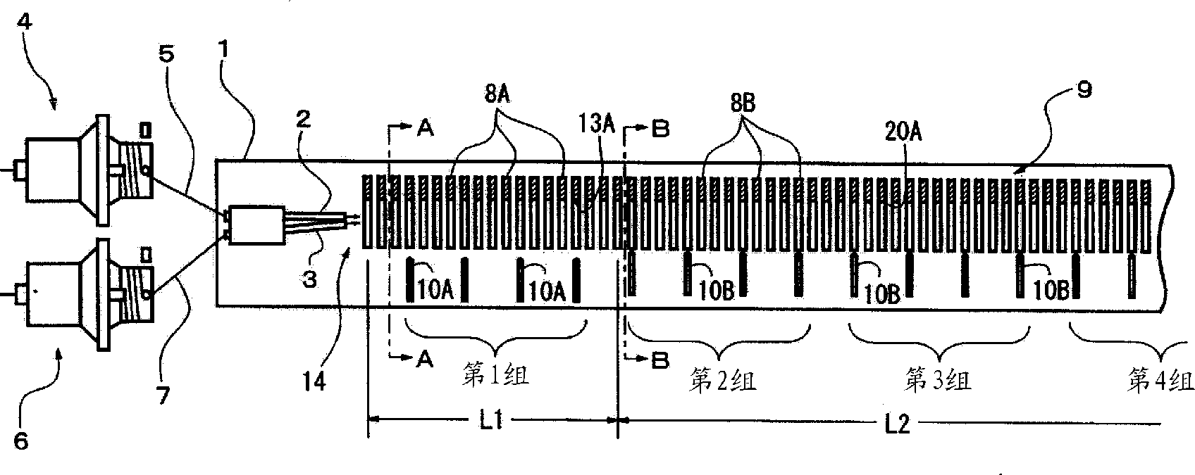
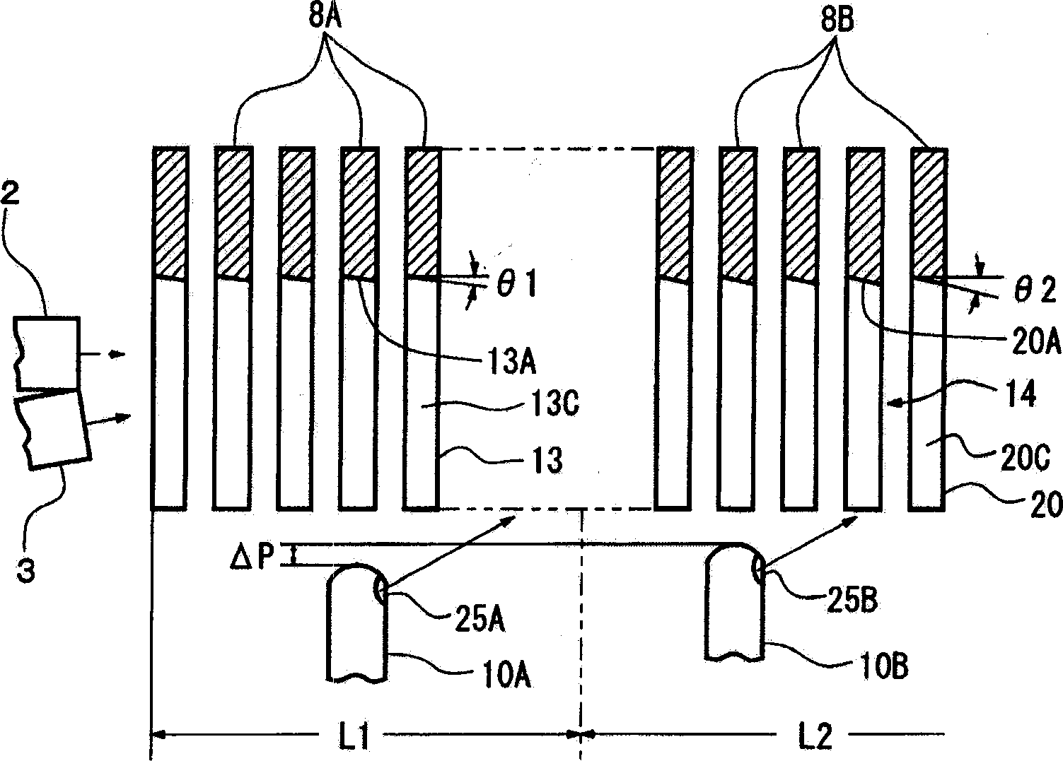
[0022] The following will refer to Figure 1 to Figure 6 The weft insertion device of the air jet loom according to the first embodiment of the present invention will be described. In the following description, the air jet loom will only be referred to as a loom from below. Reference figure 1 , Shows the weft insertion device of the air jet loom, the lower side of the figure corresponds to the front of the loom, where the woven cloth is picked up, and the upper side of the figure corresponds to the back of the loom, where it is released Warp.

[0023] The weft insertion device includes two weft insertion nozzles 2, 3 installed on the sley 1 of the loom. The weft insertion nozzle 2 extends parallel to the weft insertion direction, and the weft insertion nozzle 3 is slightly inclined with respect to the weft insertion direction, so that the air ejected from the nozzle 3 is slightly directed toward the rear of the loom. The weft yarn 5 drawn out from the weft tube (not shown) and...


PUM


Abstract

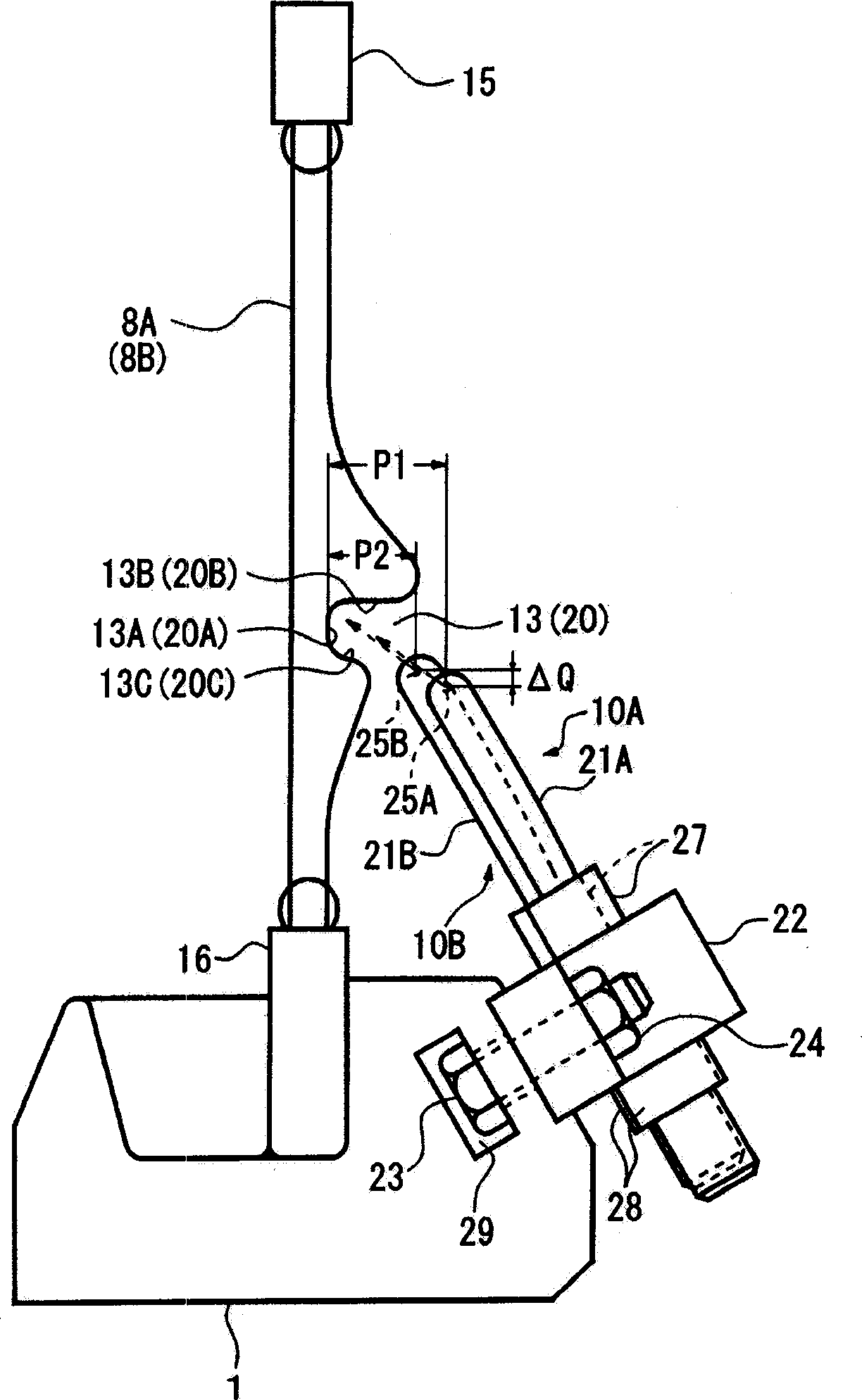
A weft insertion device of an air-jet loom comprises a plurality of dents, each of which has a guiding recess forming a weft thread path which is divided into a first zone and a second zone located at the downstream of the first zone. The inclination angle of the innermost wall of each guiding recess in the first zone is smaller than the inclination angle of the innermost wall of each guiding recess in the second zone. And, distance between an orifice of each auxiliary nozzle before the first zone and any innermost wall situated in the first zone and adjacent to the orifice is larger than thedistance between an orifice of each auxiliary nozzle before the second zone and any innermost wall situated in the second zone and adjacent to the orifice.

Description

Technical field [0001] The present invention relates to a weft insertion device of an air-jet loom, wherein the weft insertion device is operable to introduce weft yarns by air jetted through a weft guide passage, which uses a weft insertion nozzle and a sub-nozzle The guide recesses of the profile reed teeth are formed. Background technique [0002] Air jet looms have been developed to ensure the stability and high speed of weft insertion. Japanese Patent Application Publication No. 5-86544 (first reference) discloses a weft insertion device for an air jet loom. The special-shaped reed of the weft insertion device includes a plurality of reed teeth arranged side by side. Each reed tooth has a guide recess recovered from the front surface of the reed tooth. Each guide recess is formed at its innermost wall and / or other walls with a surface that is inclined so that the guide recess becomes narrow in the weft insertion direction. The weft insertion path is divided into a first ...

Claims


Application Information

Patent Timeline
Patent Type & Authority Applications(China)
IPC IPC(8): D03D47/30D03D49/62
CPCD03D47/30D03D47/302D03D47/278D03D49/62
Inventor 牧野功高木信次
Owner TOYOTA IND CORP
Learn More