Process and stretching device for holding a weft thread

A stretching device and weft yarn technology, applied in the field of stretching devices, can solve the problems of deformation of reed teeth, improper formation of intermediate spaces, and disturbances, etc., and achieve the effects of reliable clamping, changing and shrinking fabric width, and avoiding deformation.

Inactive Publication Date: 2008-03-12
SULTEX AG
View PDF1 Cites 9 Cited by
  • Summary
  • Abstract
  • Description
  • Claims
  • Application Information

AI Technical Summary

Problems solved by technology

The stretching device shown in the document JP8-113852 has the disadvantage that, due to the improper formation of the intermediate spaces between the reed teeth, disturbances occur, so that a reliable reception of the weft thread in the opening of the capture tube cannot be guaranteed
On the other hand, if the spaces between the dents are made sufficiently large, there is the risk of irreversible deformation of the dents and fabric defects appear at this point and the fabric width increases over time at later positions

Method used


Image

  • Process and stretching device for holding a weft thread

Examples


Embodiment Construction

[0020] best practice

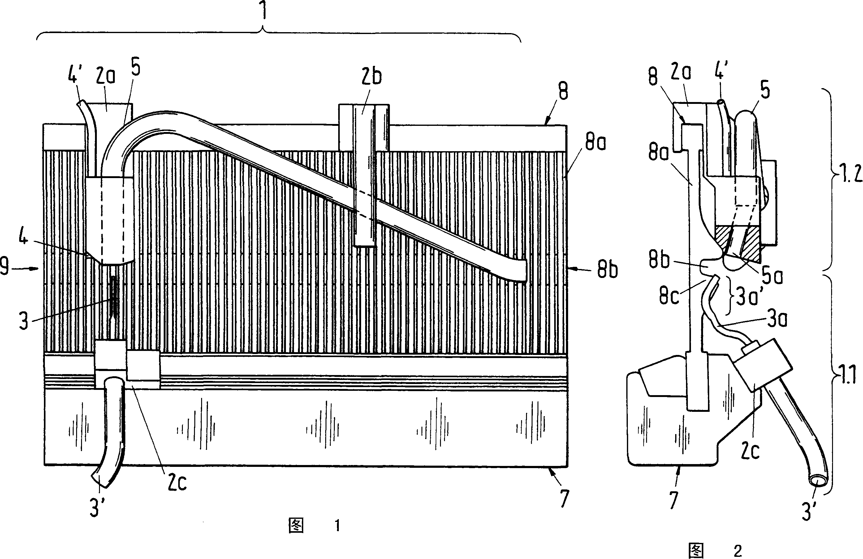
[0021] Shown in accompanying drawings 1 and 2 is the embodiment of the stretching device of the present invention for clamping the weft thread introduced into an air-jet loom provided with a reed 8 . The steel reed 8 includes a plurality of reed teeth 8a, such as shown in FIG. 1 , and the steel reed 8 is placed on the sley 7 . The stretching device according to the invention comprises a capture part 1.2 with a capture channel 5 and a nozzle part 1.1 with a nozzle 3 having a nozzle opening whose blowing direction is offset from the weft insertion direction 9. With the aid of the nozzle 3 , the end portion of the weft thread on the capture side can deviate from the weft insertion direction 9 and be blown into the receiving opening 5 a of the capture channel 5 . As shown in Fig. 2, the receiving opening 5a may be arranged side by side with the nose of the upper reed.

[0022] In addition, the stretching device 1 comprises at least one fixed part for fixin...


PUM


Abstract

The present invention relates to a method for clamping the abb which is leaded to the inner side of the air-jet loom with reed (8). In the method, the abb which is leaded to the inner side of the air-jet loom deviates from the filling insertion direction (9) and is blown into the receiving opening (5a) in the catching channel (5), and is clamped therein. The positions of the nozzle (3) and the catching channel (5) are matching with the expected fabric width in the width range of the reed. In the assigned method the nozzle (3) and the catching channel (5) are configured at the beating-up side of the reed (8).

Description

technical field [0001] The invention relates to a method of clamping an introduced weft thread according to the preamble of claim 1 , and to a corresponding stretching device according to the preamble of claim 6 , and to a loom implementing the method or provided with a stretching device. Background technique [0002] In an air-jet loom, the weft thread drawn from the yarn storage device is accelerated through the main nozzle and the tandem nozzle and inserted into the shed, where the weft thread is further conveyed by means of so-called auxiliary nozzles or relay nozzles. During weft insertion, the weft thread is guided in a weft thread channel formed in the reed. Behind the reed is usually provided a stretching device for stretching the end portion of the weft thread on the receiving side and clamping it tightly. In the stretching device (the stretching device is often referred to as catcher or clamping device), the end part of the weft thread on the receiving side engage...

Claims


Application Information

Patent Timeline
Patent Type & Authority Applications(China)
IPC IPC(8): D03D47/34D03D47/30
CPCD03D47/308
Inventor U·沙伊克
Owner SULTEX AG
Why Eureka
Try Eureka