Specimen holder assembly

a specimen and assembly technology, applied in the field of specimen holder assembly, can solve the problems of specimen movement, high magnification, and difficult translation, and achieve the effect of increasing the accuracy with which specimens are supported in a prescribed location

Inactive Publication Date: 2011-10-20
UNIV OF SHEFFIELD
View PDF1 Cites 31 Cited by
  • Summary
  • Abstract
  • Description
  • Claims
  • Application Information

AI Technical Summary

Benefits of technology

Some embodiments of the invention have the advantage that a specimen located in a beamline such as an electron, X-ray or proton beamline may be rotated about a precise axis substantially normal to an axis of the beamline without a region of interest of the specimen moving more than a prescribed distance in a direction normal to the axis (a z-axis) of the beamline. In some embodiments this has the advantage that an amount of adjustment of the position of the specimen with respect to the field of view of a microscope is reduced during a process of acquiring tomographic images of the region of interest relative to known tomography systems.
The use of piezoelectric actuators has the advantage that sub-nanometre precision may be achieved in respect of movement of a specimen.
In some embodiments the presence of a tertiary translator has the advantage that the first axis may be rotated into an orientation whereby it is substantially parallel to an axis of rotation of the goniometer.
Thus in some embodiments the controller is arranged automatically to maintain the specimen is a prescribed location upon command by a user. This has the advantage that an accuracy with which a specimen is supported in a prescribed location is increased relative to manual control of the location of the specimen.

Problems solved by technology

Indeed, the problem of tilt-induced specimen translation is exacerbated at high magnifications (e.g. of the order of 100 k or more).
Such translation is often not easy, and sometimes impossible, depending upon how far a region of interest of a specimen has moved with respect to the field of view.
Undesirable movement of the specimen may also occur due to drift and / or backlash of mechanical gears of specimen rotation and / or translation mechanisms.
Simultaneous achievement of eucentric height and height of minimum aberrations is not always possible.
Prior art systems have the disadvantage that rotation of a specimen about the axis 7A of the holder assembly can result in excessive movement of the specimen in the x-y plane.
Furthermore, the amount of this movement is typically not predictable.
In addition, prior art systems allow tilt of a specimen over only a limited angular range.
A fundamental limitation of known specimen holder assemblies is that tilt is imposed macroscopically on the entire holder assembly.
Prior art systems also have the disadvantage that a specimen or part of a specimen cannot be rotated and translated against a second specimen or a second part of a specimen.

Method used


Image

  • Specimen holder assembly
  • Specimen holder assembly
  • Specimen holder assembly

Examples


Embodiment Construction

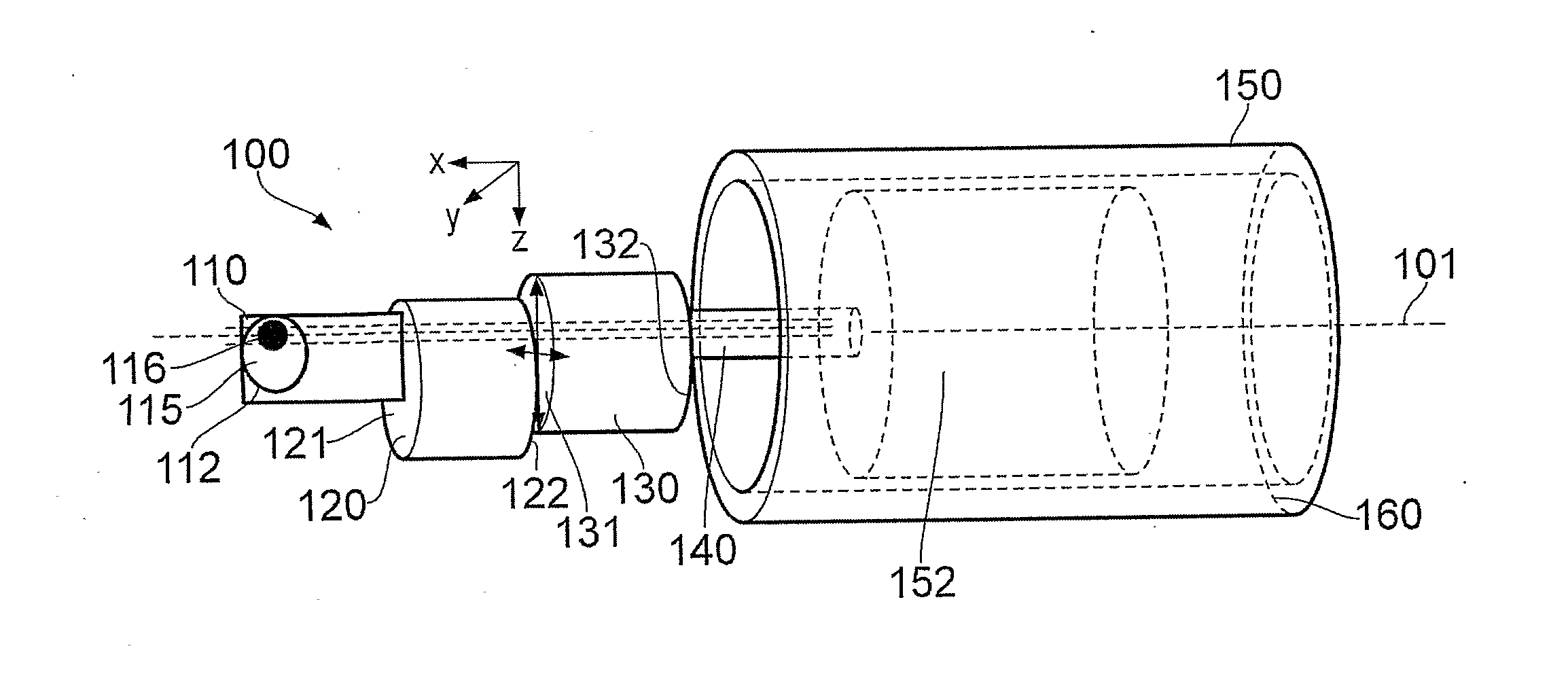
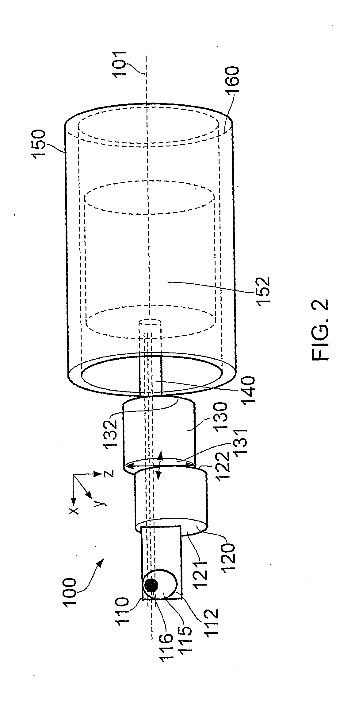
In one embodiment of the invention a holder assembly 100 is provided (FIG. 2) having a specimen mount portion 110 arranged to couple a specimen element 115 thereto. The mount portion 110 has an aperture formed therethrough over which a specimen element 115 is placed and fixedly attached thereto by means of an annular ring element 112.

In some embodiments the mount portion 110 is provided in a modular form and allows fixing of a specimen element 115 thereto in one or more different ways.

In some embodiments a specimen element 115 is provided in the form of a conventional support grid that may be coupled to a rod member which may in turn be coupled to the mount portion 110 of the holder assembly by insertion of the rod into a receiving aperture, for example by screwing into a tapped bore.

Other methods of securing the specimen element 115 to the mount portion 110 are also useful, including spring clips, screw plates and other fixing elements.

In the embodiment of FIG. 2 the mount portion ...


PUM

PropertyMeasurementUnit
angleaaaaaaaaaa
angleaaaaaaaaaa
tilt anglesaaaaaaaaaa

Abstract

A specimen holder assembly (500) suitable for tomographic inspection of a specimen in a transmission electron microscope comprising: a body portion (501) in the form of an elongate member arranged to be removably insertable into the column of the microscope; and a manipulator portion having a first axis, the manipulator portion comprising: a specimen mount portion (510) configured to support the specimen; a specimen translation assembly operable to translate the specimen mount portion with respect to the body portion; and a specimen rotation assembly (540) coupled to the body portion and to the specimen translation assembly (530), the specimen rotation assembly being operable to rotate the specimen translation assembly relative to the body portion about the first axis.

Description

FIELD OF THE INVENTIONThe present invention relates to a specimen tilt system. In particular but not exclusively the invention relates to a specimen tilt system for use in performing 3D electron tomographical or other high tilt range microscopic inspections of a specimen.BACKGROUNDElectron tomography has emerged as a powerful technique for specimen (or ‘sample’) analysis since it enables 3D information in respect of the microstructural characteristics of a specimen to be obtained from two dimensional projection images. According to the technique, projection image data is obtained from a region of interest of a specimen as viewed along a plurality of different directions. Typically, a specimen under irradiation by a beam of electrons is rotated by incremental amounts with respect to the beam about an axis. Images of the specimen are recorded at successive angles of rotation. Images so obtained are subsequently used to reconstuct a 3D model of the specimen.It is advantageous to be abl...

Claims


Application Information

Patent Timeline
Patent Type & Authority Applications(United States)
IPC IPC(8): G01N23/00
CPCG21K7/00H01J37/20H01J37/26H01J2237/20207H01J2237/20214H02N2/0095H01J2237/20242H01J2237/20264H01J2237/20285H01J2237/20292H01J2237/2617H01J2237/20221
Inventor MOEBUS, GUENTERWEI, GUANXU, XIAOJINGWANG, JING JINGGAY, RALPHLOCKWOOD, ALDEN JAMESINKSON, BEVERLEY
Owner UNIV OF SHEFFIELD
Why Eureka
Try Eureka