Multi-mode clutch

A clutch and outer ring technology, applied in the field of clutches, can solve problems such as single working mode of roller clutches

Pending Publication Date: 2018-01-05
JIANG SU NAN FANG BEARING CO LTD
View PDF0 Cites 1 Cited by
  • Summary
  • Abstract
  • Description
  • Claims
  • Application Information

AI Technical Summary

Problems solved by technology

[0003] The technical problem to be solved by the present invention is: in order to solve the problem that ...

Method used


Image

  • Multi-mode clutch
  • Multi-mode clutch
  • Multi-mode clutch

Examples


Embodiment 1

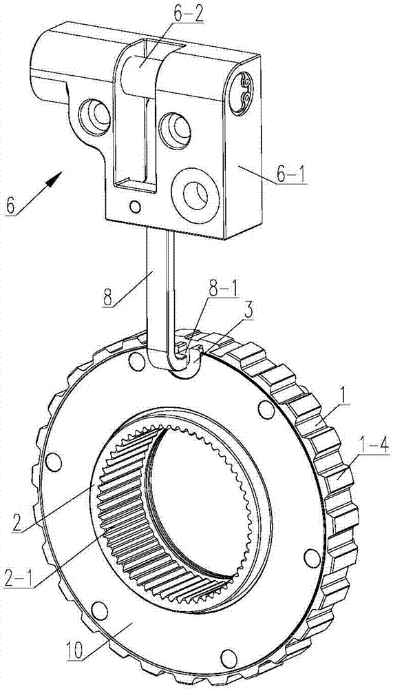
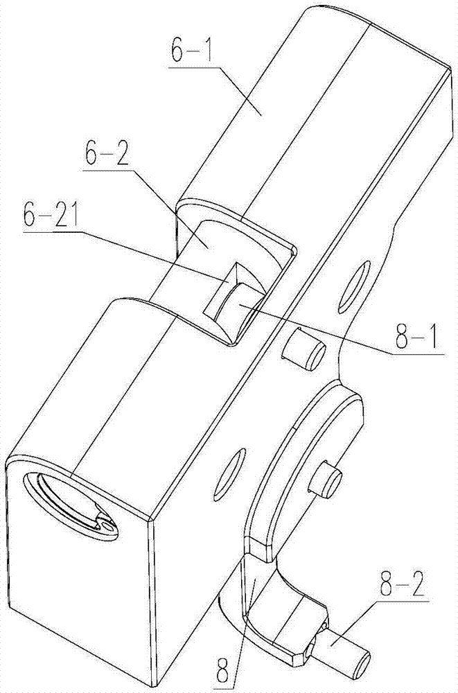
[0034] Such as Figure 1-9 As shown, a multi-mode clutch includes a clutch body and an actuator;

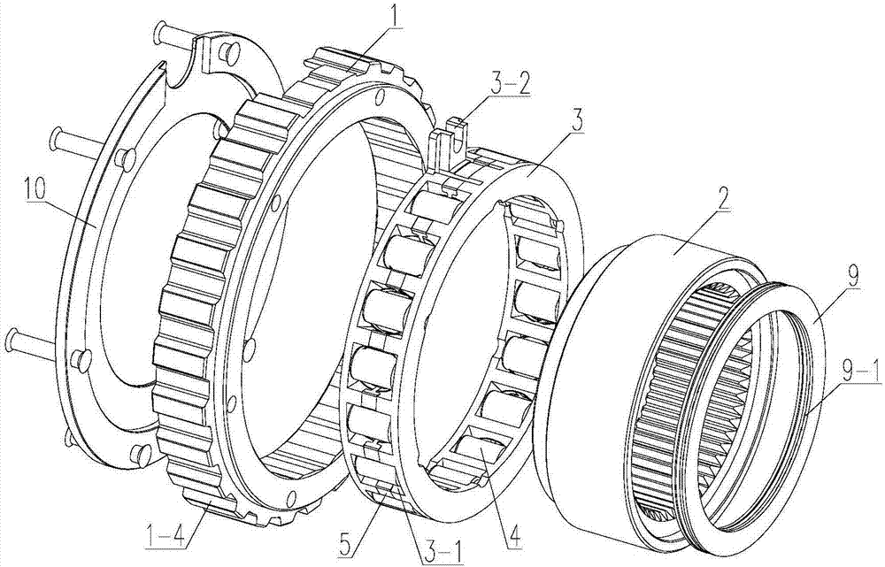
[0035] The clutch body includes an outer ring 1 and an inner ring 2 arranged coaxially, and a control ring 3 is arranged between the outer ring 1 and the inner ring 2. The outer peripheral surface of the control ring 3 runs through a number of windows 3-1 along its circumferential direction. 3-1 is equipped with a roller 4, and the inner ring wall of the outer ring 1 has a number of cavities 1-1 corresponding to the rollers 4;

[0036] The distance from the middle part of the cavity bottom 1-11 in the cavity 1-1 to the outer wall of the inner ring 2 is greater than the diameter of the roller 4, and the left side 1-12 of the cavity 1-1 is from the cavity bottom 1-11 to the left The side surface 1-12 gradually inclines toward the inner ring 2, and the right side 1-13 of the cavity 1-1 gradually inclines toward the inner ring 2 from the cavity bottom 1-11 to the right side 1-13;

...


PUM


Abstract

The invention relates to the technical field of clutches, in particular to a multi-mode clutch, which includes a clutch body and an actuator; the clutch body includes an outer ring and an inner ring coaxially arranged, a control ring is arranged between the outer ring and the inner ring, and the control ring There are several windows running through the outer peripheral surface along its circumferential direction, and a roller is arranged in each of the several windows, and there are several cavities corresponding to the rollers on the inner ring wall of the outer ring; the middle part of the cavity bottom in the cavity to the inner ring The distance between the walls of the outer ring is greater than the diameter of the rollers, the left side of the cavity gradually inclines toward the inner ring from the cavity bottom to the left side, and the right side of the cavity gradually inclines toward the inner ring from the cavity bottom to the right side ; With the rotation of the control ring, the multi-mode clutch of the present invention makes the rollers on it be in three different working positions in the cavity, so that the clutch has three working modes, and the control ring is driven to rotate by the actuator through the driving rod , and then realize the free switching of the three working modes of the clutch.

Description

technical field [0001] The invention relates to the technical field of clutches, in particular to a multi-mode clutch. Background technique [0002] The transmission device is generally used to transmit the torque of the active unit to the load. At present, there is at least one clutch in the transmission device to transmit the torque. When the power is input from the input shaft, if the clutch is in the meshing state, the power can be transmitted from the clutch to the output. If the clutch is in a non-engaged state, power cannot be transmitted between the input shaft and the output shaft. Roller clutches The existing roller clutches are usually used as one-way or overrunning clutches to provide certain conditions for the transmission shaft and the output shaft. However, the working mode of this type of roller clutch is relatively single, and its adaptability is poor, so it cannot be applied to transmission devices with complex transmission relationships. Contents of the ...

Claims


Application Information

Patent Timeline
IPC IPC(8): F16D23/12F16D11/16F16D25/12
Inventor 刘义臧新群郭宏军郭恒天
Owner JIANG SU NAN FANG BEARING CO LTD
Why Eureka
Try Eureka