Head-mounted display device and system

A head-mounted display and device technology, applied in the field of head-mounted display devices and systems, to achieve the effect of free switching

Active Publication Date: 2016-07-27
广州华视光学科技有限公司
View PDF6 Cites 17 Cited by
  • Summary
  • Abstract
  • Description
  • Claims
  • Application Information

AI Technical Summary

Problems solved by technology

However, there are still challenges in how to integrate the realistic superimposition of stereoscopic images into the vision to make the virtual stereoscopic images look realistic in the real world.

Method used


Image

  • Head-mounted display device and system
  • Head-mounted display device and system
  • Head-mounted display device and system

Examples


Embodiment 1

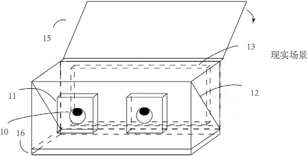
[0036] Such as figure 1 As shown, the head-mounted display device of this embodiment includes an optical system part, which includes a display 16 , a light-splitting optical film layer 12 , a front lens group 11 , a rear lens group 13 and a light-shielding film layer 15 .

[0037] Wherein, the display 16 is set in a direction outside the range of the user's line of sight, specifically, it can be set in figure 1 The unit is shown in bottom position, top position, or set to the side.

[0038] In one embodiment, the display 16 may be a liquid crystal display screen, an organic light-emitting diode display screen, an electronic ink screen, or a micro-projection device integrated on the head-mounted display device; wherein, the liquid crystal display screen may be flat In another embodiment, the display 16 can be a mobile phone, a tablet computer, a small computer screen, or other small display screens that are set independently from the head-mounted display device. When the disp...

Embodiment 2

[0056] Such as Figure 5 , 6 As shown, the technical solution of this embodiment is basically the same as that of Embodiment 1, and the main difference is that the head-mounted display device of this embodiment also includes: a filter film layer group 14, which is used to control the reality observed by the user. The brightness of the imagery of the world scene. Specifically, for balancing the visual brightness and contrast of real-world scenes and mixed (augmented) reality patterns.

[0057] Wherein, the filter film layer group 14 is arranged on the other side of the light-splitting optical film layer 12, and is located between the light-splitting optical film layer 12 and the rear lens group 13, or between the rear lens group 13 and the light-shielding film layer 15 between.

[0058] Such as Figure 7 As shown, in one embodiment, the filter film layer group 16 is composed of two linear filter arrays. By rotating, the angle between the polarization directions of the two ...


PUM


Abstract

The invention discloses a head-mounted display device and system.The head-mounted display device comprises a displayer, a light splitting optical film layer, a front lens set, a rear lens set and a shading film layer.When the shading film layer is closed, image information on the displayer is reflected by the light splitting optical film layer to the front lens set, and after modification by the front lens set, a user can observe the amplified image information through the front lens set, so that virtual reality scene display is realized; when the shading film layer is opened, the image information on the displayer is reflected by the light splitting optical film layer to the front lens set, meanwhile, a real world scene is transmitted by the light splitting optical film layer to the front lens set after being adjusted by the rear lens set, and after modification by the front lens set, the user can observe a mixed real scene formed after superposition of the real world scene and the image information through the front lens set.Through the head-mounted display device and system, free switching between augmented reality, virtual reality and mixed reliability can be realized.

Description

technical field [0001] The present invention relates to a head-mounted display device that is worn on a user's head to provide virtual images, and more particularly, relates to a head-mounted display device and system that can realize free switching between augmented reality, virtual reality and mixed reality. Background technique [0002] Virtual reality technology (virtual reality, referred to as VR), is the use of optical technology to enable a small-sized screen to achieve a large-screen visual effect, providing an immersive virtual environment, such as Oculus virtual reality glasses. [0003] Augmented reality technology (augmented reality, referred to as AR), is to allow users to simultaneously receive and display computer information while observing the real world. [0004] Mixed reality technology (Mixedreality, referred to as MR), allows people to see the real world and the virtual world at the same time, and people can also interact with these virtual objects, such...

Claims


Application Information

Patent Timeline
Patent Type & Authority Applications(China)
IPC IPC(8): G02B27/01G06F3/01
CPCG02B27/017G02B2027/0134G02B2027/0141G06F3/011G06F2203/012
Inventor 范杭
Owner 广州华视光学科技有限公司
Why Eureka
Try Eureka