Pneumatic tire

A technology for pneumatic tires and tires, applied in tire parts, tire treads/tread patterns, transportation and packaging, etc. problem, to achieve the effect of improving partial wear resistance and inhibiting soil dumping.

Active Publication Date: 2018-01-09
TOYO TIRE & RUBBER CO LTD
View PDF12 Cites 5 Cited by
  • Summary
  • Abstract
  • Description
  • Claims
  • Application Information

AI Technical Summary

Problems solved by technology

However, if bridges are provided, the horizontal grooves will become shallower in this part, and the groove volume will decrease correspondingly, which will be the main cause of the decrease in soil discharge performance and traction performance.

Method used


Image

  • Pneumatic tire
  • Pneumatic tire
  • Pneumatic tire

Examples


Embodiment 2

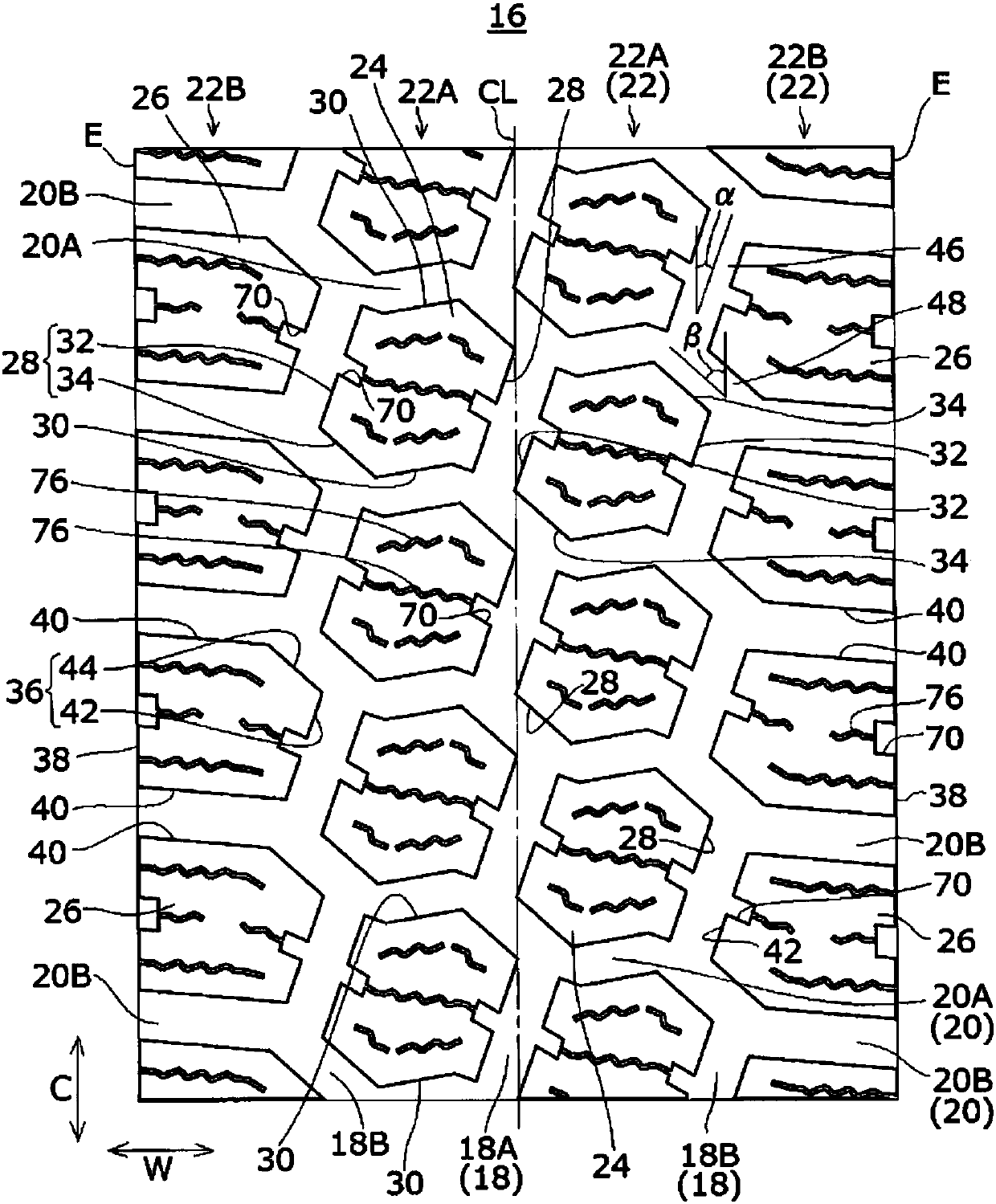
[0062] The tire of Example 2 has Figure 1-7 Features of the embodiment shown in . In embodiment 2, set the groove width of main groove=11.5mm, the depth of main groove=16.5mm, for the first~the 3rd shallow groove part 52,54,56 (expressed as " three grades " in table 1 ), set H1=H3=9.9mm, H2=7.9mm, L1=8.5mm, L2=8.0mm, L3=4.5mm, L0=35.2mm, G=1.0mm, D=0.6mm, make the second shallow The center position M1 of the groove portion is shifted by 2.0 mm toward the tire contact edge E side with respect to the center position M0 of the lateral groove. In the tire of Example 1, the center position M1 of the second shallow groove coincides with the center position M0 of the lateral groove, and has the same structure as that of the tire of Example 2 in other respects. In the tire of Comparative Example 1, the first to third shallow grooves 52 , 54 , and 56 are not provided in the transverse groove 20B between the shoulder blocks 26 , but instead, one stage with a depth of 8.9 mm and a len...


PUM


Abstract

Provided is a pneumatic tire. In a shoulder block row in which a plurality of shoulder blocks are disposed in a tire circumferential direction, a lateral groove between adjacent shoulder blocks in thetire circumferential direction has a first shallow groove portion that is positioned on a side close to a main groove and has a depth shallower than that of the main groove, a third shallow groove portion that is positioned on a side close to a tire ground contact end and has a depth shallower than that of the main groove, and a second shallow groove portion that is positioned between the first shallow groove portion and the third shallow groove portion, and has a depth shallower than those of the first shallow groove portion and the third shallow groove portion.

Description

technical field [0001] This embodiment relates to a pneumatic tire. Background technique [0002] Among pneumatic tires, there is known a so-called block tire in which rows of blocks are provided on the tread portion by main grooves extending in the tire circumferential direction and transverse grooves intersecting the main grooves (see Japanese Patent Laid-Open Heisei No. 5-085110, Japanese Patent Publication No. 2008-222090, Japanese Patent Publication No. Heisei 11-059135). [0003] In tires with these block patterns, in order to improve the rigidity of the blocks and improve the partial wear resistance, it is proposed to provide bridges in the transverse grooves between adjacent blocks in the tire circumferential direction to connect the front and rear blocks (refer to Japanese Patent Publication No. 2012-076739). However, if a bridge is provided, the horizontal groove becomes shallow in this part, and the groove volume becomes smaller correspondingly, which becomes a ...

Claims


Application Information

Patent Timeline
Patent Type & Authority Applications(China)
IPC IPC(8): B60C11/03B60C11/04B60C11/11B60C11/13
CPCB60C11/1369B60C2011/0369B60C2011/1254B60C11/11B60C11/0309B60C11/1236B60C2011/1213B60C2011/1361B60C11/1204B60C11/1353
Inventor 藤冈刚史
Owner TOYO TIRE & RUBBER CO LTD
Why Eureka
Try Eureka