Power cabinet instrument fixing support
A technology for fixing brackets and power cabinets, applied in electrical components, substation/switch layout details, etc., can solve problems such as troublesome wire installation and fixing, inconvenient instrument maintenance, affecting instrument equipment maintenance, etc., to facilitate maintenance, improve work efficiency, and operate simple effect
- Summary
- Abstract
- Description
- Claims
- Application Information
AI Technical Summary
Problems solved by technology
Method used
Image

Examples
Embodiment Construction
[0014] The following will clearly and completely describe the technical solutions in the embodiments of the present invention with reference to the accompanying drawings in the embodiments of the present invention. Obviously, the described embodiments are only some, not all, embodiments of the present invention.
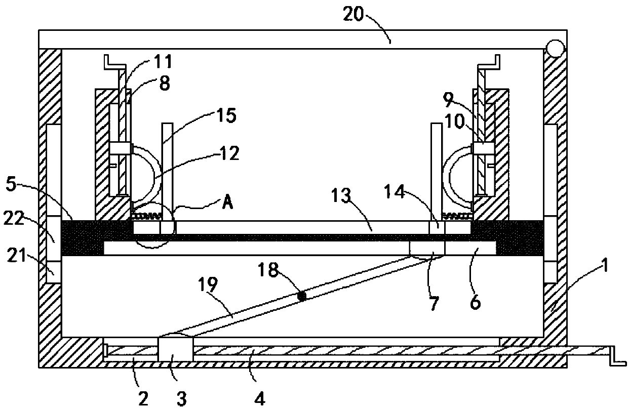
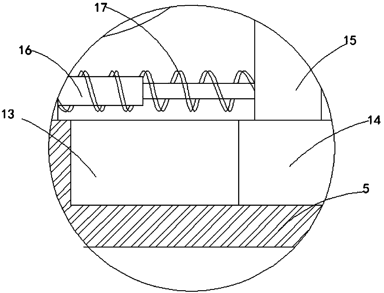
[0015] refer to Figure 1-2 , a kind of power cabinet meter fixing bracket, including a cabinet body 1, the bottom of the cabinet body 1 is horizontally provided with a first chute 2, the first chute 2 is provided with a first slider 3, and the side of the first slider 3 The wall is provided with a first threaded hole connected left and right, and the first threaded hole is internally threaded with a first threaded rod 4, one end of the first threaded rod 4 is rotatably connected with one end side wall of the first chute 2, and the first threaded The other end of rod 4 passes the other end sidewall of first chute 2 and extends to the outside of cabinet 1, and the fir...
PUM
 Abstract
Description
Claims
Application Information
 - Generate Ideas
- Intellectual Property
- Life Sciences
- Materials
- Tech Scout
- Unparalleled Data Quality
- Higher Quality Content
- 60% Fewer Hallucinations
Browse by: Latest US Patents, China's latest patents, Technical Efficacy Thesaurus, Application Domain, Technology Topic, Popular Technical Reports.
© 2025 PatSnap. All rights reserved.Legal|Privacy policy|Modern Slavery Act Transparency Statement|Sitemap|About US| Contact US: help@patsnap.com