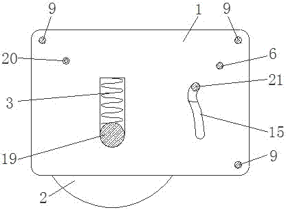
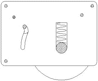
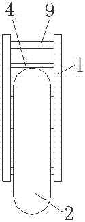
Inlaid type muting automatic buffering pulley device
A buffer wheel and pulley technology, which is applied to the suspension devices of wing sashes, switches with brakes, door/window accessories, etc., can solve problems such as poor adaptability, and achieve good mute effect, good adaptability, and operation process. simple effect
- Summary
- Abstract
- Description
- Claims
- Application Information
AI Technical Summary
Problems solved by technology
Method used
Image
Examples
Embodiment 1
[0070] In this embodiment, the second mounting piece 26 is a square mounting piece, such as Figure 14 As shown, three second mounting holes 27 are provided in the middle of the second mounting piece 26, and the number of the second mounting piece 26 is one. Four third mounting holes 28 are respectively provided at both ends of the second mounting piece 26 in the longitudinal direction. The positions of the three second mounting holes 27 provided in the middle of the second mounting piece 26 correspond to the positions of the first mounting holes 23 provided on the first mounting piece 16 respectively.
[0071] According to the thickness of the door body, select the second installation piece 26 whose width matches the thickness of the door body, and the width of the second installation piece 26 does not exceed the thickness of the door body.
[0072] First use the fixing screws 29 to respectively connect each second mounting hole 27 on the second mounting piece 26 with the co...
Embodiment 2
[0098] Different from the above embodiments, the second mounting piece 26 in this embodiment is a long and narrow mounting piece, such as Figure 17 As shown, the two ends of the length direction of the second mounting piece 26 are respectively provided with a third mounting hole 28, and the middle part of the second mounting piece 26 is provided with a second mounting hole 27. When the second mounting piece 26 is installed horizontally, the second mounting piece The number of 26 can be selected as two. When the second installation piece 26 is installed obliquely, the number of the second installation piece 26 can be selected as three.
[0099] First use fixing screws 29 to respectively connect the second mounting holes 27 on each second mounting piece 26 with the first mounting holes 23 on the first mounting piece 16, and the fixing screws 29 can be screwed into the first mounting holes 23 with internal threads. In the installation hole 23 , the second installation piece 26 ...
Embodiment 3
[0104] Different from the above embodiments, the second mounting piece 26 in this embodiment is an L-shaped mounting piece composed of a short arm 31 and a long arm 32, such as Figure 20 As shown, the long arm 32 of the second mounting piece 26 is provided with a third mounting hole 28, the short arm 31 of the second mounting piece 26 is provided with a second mounting hole 27, and the number of the second mounting piece 26 is not less than two. .
[0105] There are three installation methods for this L-shaped mounting piece.
[0106] The first installation method: the quantity of the second installation pieces 26 is selected as two, and when the long arms 32 of the two second installation pieces 26 are folded together, the long arms 32 of the two second installation pieces 26 all face On the same side, the long arm 32 is on both sides of the housing 1 when unfolded, such as Figure 22 shown.
[0107] The second installation method: the quantity of the second installation ...
PUM
 Abstract
Description
Claims
Application Information
 - R&D
- Intellectual Property
- Life Sciences
- Materials
- Tech Scout
- Unparalleled Data Quality
- Higher Quality Content
- 60% Fewer Hallucinations
Browse by: Latest US Patents, China's latest patents, Technical Efficacy Thesaurus, Application Domain, Technology Topic, Popular Technical Reports.
© 2025 PatSnap. All rights reserved.Legal|Privacy policy|Modern Slavery Act Transparency Statement|Sitemap|About US| Contact US: help@patsnap.com


