Device for tunnel excavation and unloading

A technology for tunnel excavation and tunneling, which is used in measuring devices, instruments, scientific instruments, etc., can solve the problems of uneven melting degree, differential distribution of surrounding rock stress performance, and insufficiency, and achieves stiffness that is not easily deformed, high stiffness, Construct simple effects

Active Publication Date: 2018-01-12
CHENGDU UNIVERSITY OF TECHNOLOGY
View PDF8 Cites 4 Cited by
  • Summary
  • Abstract
  • Description
  • Claims
  • Application Information

AI Technical Summary

Problems solved by technology

[0007] The purpose of the present invention is to provide a test device for simulating tunnel excavation and unloading, which solves the problem of only simulating the instantaneous excavation of the full section during model excavation, thereby ignoring the time-space effect of surrounding rock deformation caused by excavation, especially for "heating and melting" As far as the method is concerned, the inhomogeneous melting degree leads to the insufficient distribution of surrounding rock stress performance differences.

Method used


Image

  • Device for tunnel excavation and unloading
  • Device for tunnel excavation and unloading
  • Device for tunnel excavation and unloading

Examples


Embodiment 1

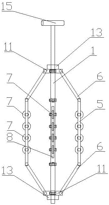
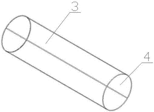
[0042] Such as figure 1 , 2 As shown, a device for unloading tunnel excavation includes a central shaft 1, a supporting structure 2 and a steel tube sheet 3. The steel tube sheet 3 is an arc-shaped sheet and has more than two sheets. The arc of the steel tube sheet 3 is the same as that to be simulated The inner wall of the tunnel is matched. Two or more steel pipe sheets 3 are successively attached to the inner wall of the tunnel to be simulated, and a cylindrical cavity 4 is formed between the two or more steel pipe sheets 3; the central axis 1 is arranged in a cylindrical shape At the center axis of the inner cavity 4, the support structure 2 includes a connecting rod 5 and a support rod 6 respectively connected to both ends of the connecting rod 5. The connecting rod 5 is fixedly installed on the central shaft 1 through the support rod 6, and the connecting rod 5 is also installed There is a bearing 7 which is connected to the inner tube wall of the steel tube sheet 3 in sli...

Embodiment 2

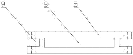
[0045] Such as figure 1 , 3 As shown, compared with embodiment 1, this embodiment optimizes the connecting rod 5, and a bearing installation through hole 8 is opened along the shaft of the connecting rod 5. There are more than two bearings 7 and they are arranged in the bearing installation through hole 8 in sequence. Inside.

[0046] In this embodiment, the multiple bearings 7 can achieve unloading more stably, and at the same time, by opening the bearing installation through holes 8, the multiple bearings 7 can be installed more neatly, avoiding the problem of large level errors between the bearings 7 .

Embodiment 3

[0048] Such as image 3 , 4 As shown in Figure 6, compared with Example 1, this embodiment optimizes the connection between the connecting rod 5 and the support rod 6. The two end faces of the connecting rod 5 are provided with limit grooves 9, and the connection between the support rod 6 and the connecting rod 5 A limit block 10 is provided, and the limit block 10 is located in the limit slot 9 and the connecting rod 5 and the limit slot 9 are fixedly connected by bolts and nuts.

[0049] In this embodiment, the support rod 6 and the connecting rod 5 are fixedly connected by bolts and nuts. At the same time, in order to adapt to the size of the simulated tunnel, the angle between the support rod 6 and the connecting rod 5 can also be adjusted. Change the position of the connecting rod 5 relative to the central axis 1. When adjusting, you only need to loosen the nut, then adjust the angle, and after the angle is adjusted, tighten the nut to fix it.


PUM


Abstract

The invention discloses a device for tunnel excavation and unloading. The device comprises a center shaft, support structures and steel tube pieces, wherein the two or more steel tube pieces are arranged and are arc-shaped pieces; the radians of the steel tube pieces are compatible with the inner wall of a tunnel to be simulated; the two or more steel tube pieces are sequentially stuck on the inner wall of the tunnel to be simulated in a surrounding way, and a cylindrical inner cavity is formed by the two or more steel tube pieces; the center shaft is arranged at a central axis of the cylindrical inner cavity; each support structure comprises a connecting rod and support rods respectively connected with the two ends of the connecting rod; the connecting rods are fixedly installed on the center shaft by means of the support rods; bearings are also installed on the connecting rods; the bearings are connected with the inner tube walls of the steel tube pieces in a sliding support way. Thedevice for tunnel excavation and unloading has the beneficial effect that the device can well replace a water bag and wax in the traditional scheme, thus realizing first loading and then excavating.

Description

Technical field [0001] The invention belongs to the technical field of underground engineering testing, and relates to the physical model test of a deep-buried high ground stress tunnel, and specifically relates to a test device for simulating tunnel excavation and unloading, which provides an excellent excavation solution for the tunnel-related physical model test, and further provides research and analysis During tunnel excavation, stress changes in surrounding rock and brittle failure characteristics such as rockburst provide scientific understanding. Background technique [0002] With the development of western my country, underground and tunnel projects in western China are gradually developing on the Tibetan Plateau. Complex geological conditions such as large burial depth and high ground stress have become major problems faced by builders and researchers. Among them, the hard and brittle rock mass In terms of high ground stress rock burst is the main engineering geological...

Claims


Application Information

Patent Timeline
Patent Type & Authority Applications(China)
IPC IPC(8): G01N33/00
Inventor 李天斌郭庚焮华春翔高进
Owner CHENGDU UNIVERSITY OF TECHNOLOGY
Why Eureka
Try Eureka