Array substrate, display panel and electronic device

A technology for an array substrate and a display panel is applied in the fields of display panels, electronic equipment, and array substrates, and can solve the problems of increasing the manufacturing cost of an embedded self-capacitive touch display panel, increasing the number of touch connecting lines and touch channels, and the like, Achieve the effect of reducing the number and the number of driving lines, ensuring touch performance, and reducing production costs

Active Publication Date: 2021-06-01
GUANGDONG OPPO MOBILE TELECOMM CORP LTD
View PDF5 Cites 0 Cited by
  • Summary
  • Abstract
  • Description
  • Claims
  • Application Information

AI Technical Summary

Problems solved by technology

[0002] The self-capacitive touch mode has been widely used in the field of display devices, but under the premise of ensuring the touch resolution, there is a requirement for the size and width of the touch unit. The existing embedded self-capacitive touch display panel Most of the included touch units adopt a square (BlockPattern) design, and the embedded self-capacitive touch panel requires a large number of touch units
[0003] In related technologies, each touch unit is connected to the corresponding touch connection line through a separate touch channel, and each effective touch connection line is connected to a touch unit and a touch channel. The increase in the number of units leads to a corresponding increase in the number of touch connection lines and touch channels, thereby increasing the production cost of the embedded self-capacitive touch display panel

Method used


Image

  • Array substrate, display panel and electronic device
  • Array substrate, display panel and electronic device
  • Array substrate, display panel and electronic device

Examples


Embodiment Construction

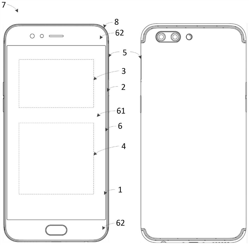
[0025] The technical solutions in the embodiments of the present application will be clearly and completely described below in conjunction with the drawings in the embodiments of the present application. Apparently, the described embodiments are only some of the embodiments of this application, not all of them. Based on the embodiments in this application, all other embodiments obtained by those skilled in the art without making creative efforts belong to the scope of protection of this application.

[0026] In the description of the present application, it should be understood that the terms "center", "longitudinal", "transverse", "length", "width", "thickness", "upper", "lower", "front", " Orientation indicated by rear, left, right, vertical, horizontal, top, bottom, inside, outside, clockwise, counterclockwise, etc. The positional relationship is based on the orientation or positional relationship shown in the drawings, which is only for the convenience of describing the a...


PUM

PropertyMeasurementUnit
electrical resistanceaaaaaaaaaa

Abstract

The present application discloses an array substrate, a display panel and an electronic device, wherein the array substrate comprises: a plurality of touch units, a plurality of touch connection lines, a plurality of resistance structures, a plurality of switching units, at least one touch chip, and A plurality of drive lines connecting the switch unit and the touch chip, each switch unit is connected with at least two touch connection lines, and each touch connection line is connected with at least two touch units and at least one resistor in the same touch column structure, and at least one of the resistance structures is connected between any two touch units connected to the same touch connection line, and the switch unit drives any touch unit connected to it through corresponding control signals in different touch time periods. The touch unit connected to the control cable. On the premise of ensuring the touch performance of the display panel, the present application reduces the number of touch connection lines and the number of driving lines required to connect the touch unit and the touch chip, thereby reducing the manufacturing cost.

Description

technical field [0001] The present application relates to the technical field of electronic equipment, in particular to an array substrate, a display panel and electronic equipment. Background technique [0002] The self-capacitive touch mode has been widely used in the field of display devices, but under the premise of ensuring the touch resolution, there is a requirement for the size and width of the touch unit. The existing embedded self-capacitive touch display panel Most of the included touch units adopt a square (BlockPattern) design, and the embedded self-capacitive touch panel requires a large number of touch units. [0003] In related technologies, each touch unit is connected to the corresponding touch connection line through a separate touch channel, and each effective touch connection line is connected to a touch unit and a touch channel. The increase in the number of units leads to a corresponding increase in the number of touch connection lines and touch chann...

Claims


Application Information

Patent Timeline
Patent Type & Authority Patents(China)
IPC IPC(8): G06F3/044G06F3/041G02F1/1333G02F1/1362
Inventor 曾元清
Owner GUANGDONG OPPO MOBILE TELECOMM CORP LTD
Why Eureka
Try Eureka