
Irregularly shaped display panel, driving method thereof and display device

A display panel and driving method technology, applied to static indicators, instruments, etc., can solve the problem of visible borders of special-shaped display panels, and achieve the effects of avoiding visible borders, reducing structural complexity, and reducing production costs

Active Publication Date: 2018-01-16
WUHAN TIANMA MICRO ELECTRONICS CO LTD
View PDF7 Cites 17 Cited by
  • Summary
  • Abstract
  • Description
  • Claims
  • Application Information

AI Technical Summary

Problems solved by technology

[0004] In view of this, the embodiments of the present invention provide a special-shaped display panel, its driving method, and a display device, which can solve the problem of visible boundaries in the existing special-shaped display panel on the premise of only using one main driver chip.

Method used


Image

  • Irregularly shaped display panel, driving method thereof and display device
  • Irregularly shaped display panel, driving method thereof and display device
  • Irregularly shaped display panel, driving method thereof and display device

Examples


specific Embodiment approach 1

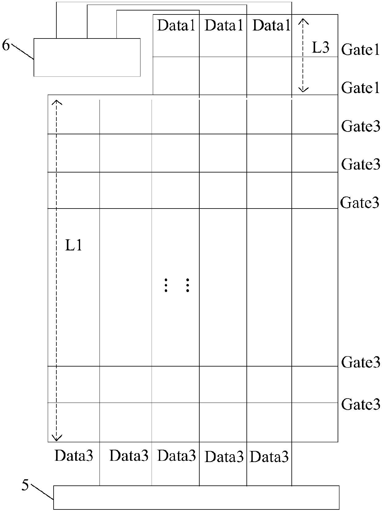
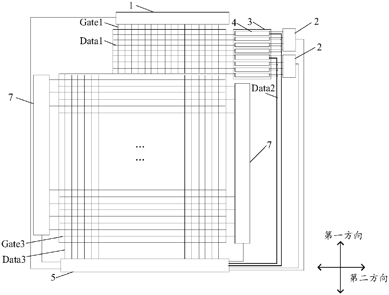
[0085] Taking the auxiliary display area including 160 first data lines Data1 extending along the row direction and 1040 first gate lines Gate1 extending along the column direction as an example, if eight 20-stage shift registers are used, it corresponds to eight second data lines. Line Data2. The charging time for one frame of the auxiliary display area is T1=20*1040*5μs=104ms. According to f=1 / T, the corresponding frame frequency f1=1 / 104ms=10Hz can be calculated.

[0086] If 16 10-level shift registers are used, it corresponds to 16 second data lines Data2. The charging time for one frame of the auxiliary display area is T2=10*1040*5μs=52ms. According to f=1 / T, the corresponding frame frequency f2=1 / 52ms=20Hz can be calculated.

[0087] Since the current frame frequency f of the special-shaped display panel is about 15 Hz, it can be deduced that the required number of second data lines Data2 should be greater than 8 and less than 16 according to f1

specific Embodiment approach 2

[0088] Taking the auxiliary display area including 1040 first data lines Data1 extending along the column direction and 160 first gate lines Gate1 extending along the row direction as an example, if eight 130-level shift registers are used, that is, corresponding to eight second data lines Line Data2. The charging time for one frame of the auxiliary display area is T1'=130*160*5μs=104ms. According to f=1 / T, the corresponding frame frequency f1'=1 / 104ms=10Hz can be calculated.

[0089] If 16 65-stage shift registers are used, it corresponds to 16 second data lines Data2. The charging time for one frame of the auxiliary display area is T2'=65*160*5μs=52ms. According to f=1 / T, the corresponding frame frequency f2'=1 / 52ms=20Hz can be calculated.

[0090] Since the current frame frequency f of the special-shaped display panel is about 15 Hz, the same derivation method as above, according to f1'<f<f2', it can be deduced that the required number of second data lines Data2 should be ...


PUM


Abstract

The embodiment of the invention provides an irregularly shaped display panel, a driving method thereof and a display device and relates to the technical field of display. A main driving chip is adopted for solving the problem of visible boundary of a present irregularly shaped display panel. A display area comprises a main display area and a secondary display area; the irregularly shaped display panel comprises first data lines, first grid lines, a first scanning unit, M second scanning units, M switch unit sets and M second data lines; the first data lines and the first grid lines are arranged in the secondary display area; the first scanning unit is connected with the main driving chip and multiple first grid lines; the control ends of the second scanning units are connected with the main driving chip; each switch unit set comprises a plurality of switch units; the control ends of the switch units of each switch unit set are connected with a plurality of output ends of the corresponding second scanning units; the first ends of the switch units of each switch unit set are connected with the first data lines; the second data lines are connected with the main driving chip and the second ends of the switch units of the corresponding switch unit set. The irregularly shaped display panel is used for realizing the image display.

Description

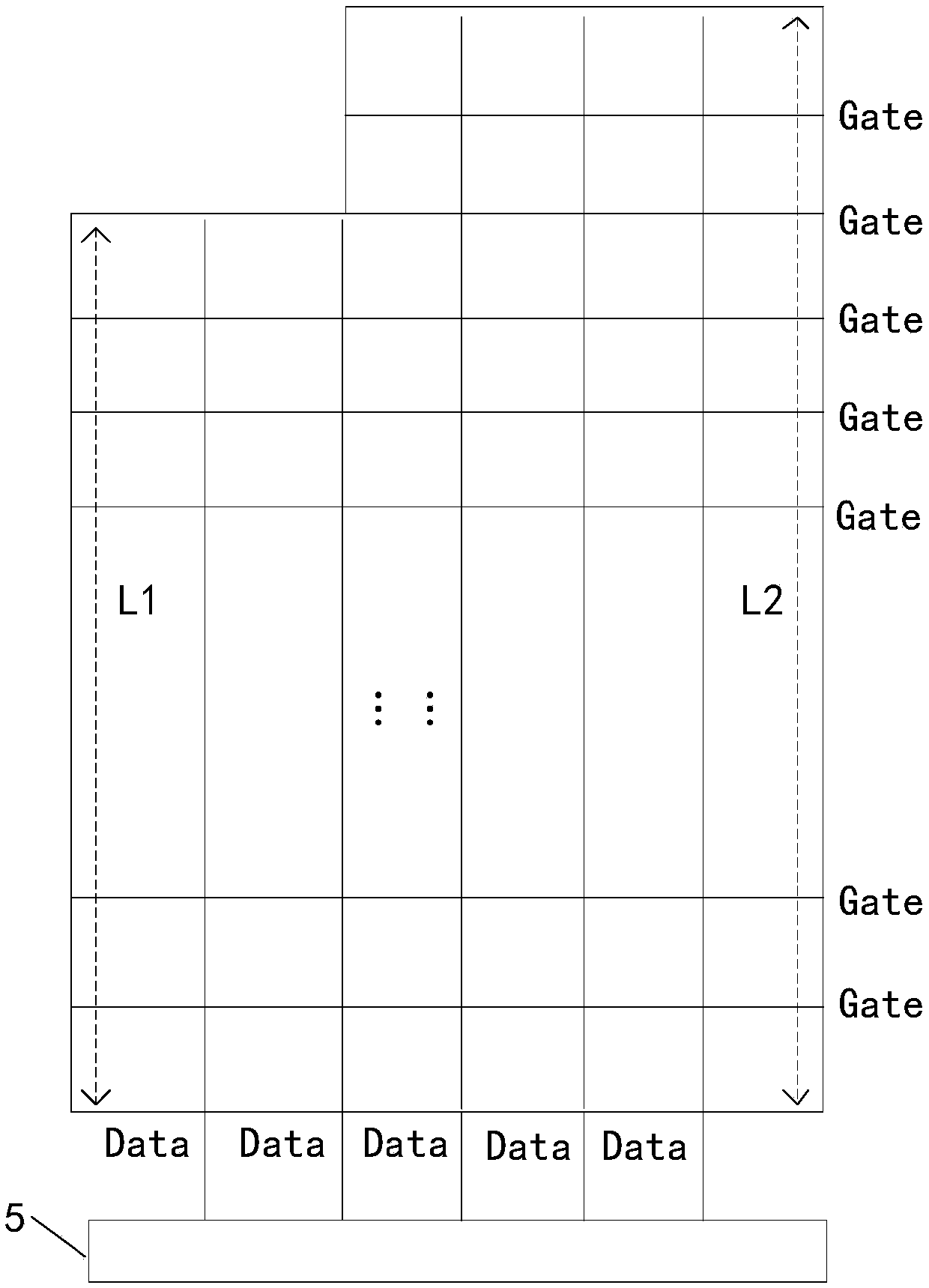
【Technical field】 [0001] The invention relates to the field of display technology, in particular to a special-shaped display panel, a driving method thereof, and a display device. 【Background technique】 [0002] With the rapid development of display technology, special-shaped display panels have been more and more widely used. Compared with the traditional display panel, the display area of ​​the special-shaped display panel includes a main display area and an auxiliary display area. Such as figure 1 As shown, taking the gate line Gate extending along the row direction and the data line Data extending along the column direction as an example, due to the irregular shape of the display area of ​​the special-shaped display panel, there are data of two lengths L1 and L2 in the special-shaped display panel. Line Data, which in turn leads to the problem of a visible boundary between the area where the data line with the length L1 is located and the area where the data line with ...

Claims


Application Information

Patent Timeline
Patent Type & Authority Applications(China)
IPC IPC(8): G09G3/36
CPCG09G2300/0426G09G2310/0286G09G3/20G09G3/3275G09G3/3685G09G2300/0408G09G2310/0275G09G2310/0297G09G2310/08G09G2330/021G09G2320/0242G09G2320/0233
Inventor 陈仲怀黄敏孙莹
Owner WUHAN TIANMA MICRO ELECTRONICS CO LTD
Learn More