
A brake structure applied to electric tool switch

A technology of electric tools and switches, which is applied in the field of brake structures, can solve problems such as damage, safety accidents, and damage to processed products, and achieve the effect of reducing the speed of the motor

Active Publication Date: 2020-06-19
SUZHOU HUAZHIJIE TELECOM +1
View PDF6 Cites 0 Cited by
  • Summary
  • Abstract
  • Description
  • Claims
  • Application Information

AI Technical Summary

Problems solved by technology

[0002] Electric tools, especially electric tools driven by motors, are usually controlled by push-type switches during operation. Usually, the switch is pressed to start the motor, and the switch is released to turn off the motor. Since the motor rotation has inertia, when the operator releases the After the switch is switched on, the motor will continue to run for a certain period of time. During this period, the electric tool is still in the process of operation, so there is a risk of safety accidents and may cause damage to the processed product. Taking the electric hammer as an example, when the operator releases the switch Finally, the motor continues to run for a period of time. During this period of time, the electric hammer still has a large vibration, and the hammer head at the front end still has a large momentum. At this time, if the operator touches the electric hammer to other objects, then Other items may be damaged due to the impact of the hammer head, and if it touches people, it may hurt the human body. Therefore, it is necessary to provide a brake structure that can stop the motor of the electric tool quickly

Method used


Image

  • A brake structure applied to electric tool switch
  • A brake structure applied to electric tool switch
  • A brake structure applied to electric tool switch

Examples


Embodiment Construction

[0017] Attached below figure 1 , describe the specific embodiment of the present invention in detail.

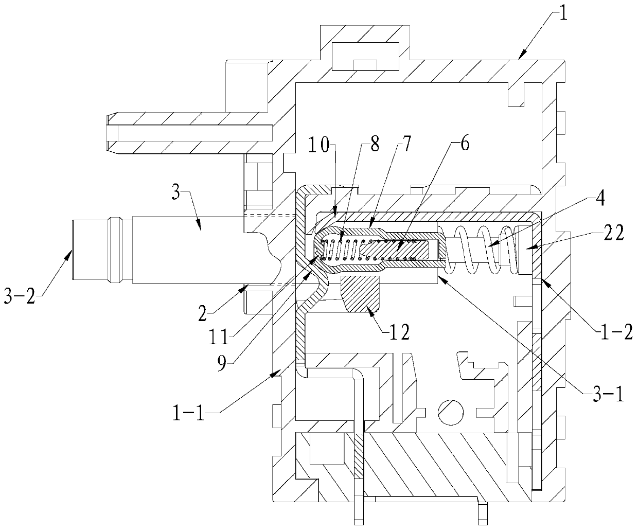
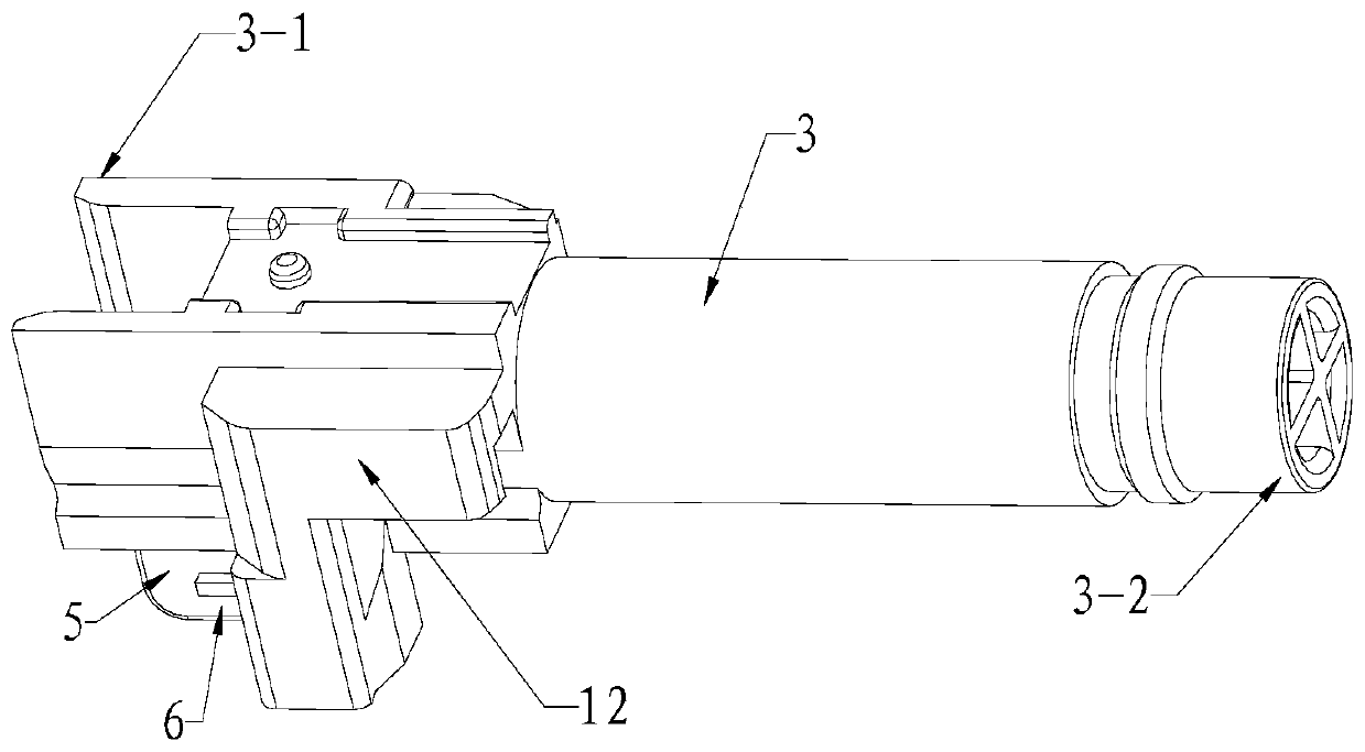
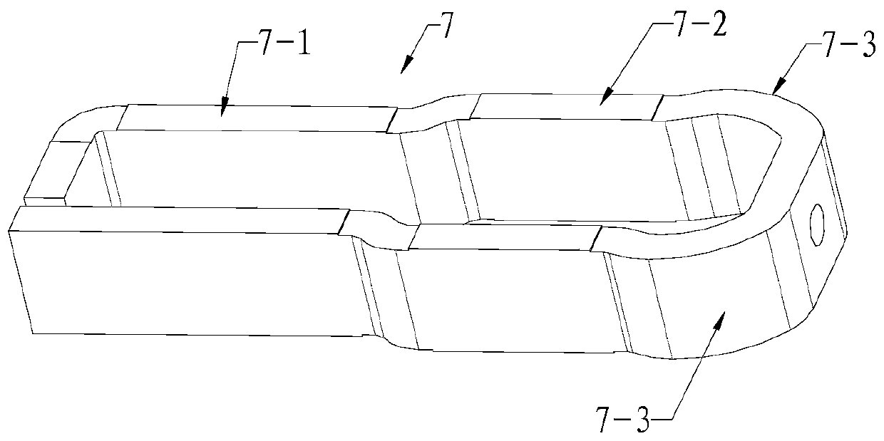
[0018] Such as Figure 1 ~ Figure 3 The brake structure shown in the electric tool switch includes a hollow housing 1, the front side plate 1-1 of the housing 1 is provided with a push rod installation hole 2 communicating with the inside, and the push rod installation hole 2 A push rod 3 is installed, one end of the push rod 3 is inserted into the casing 1, and the other end extends out of the casing 1, one end of the push rod 3 inside the casing 1 is the push rod inner end 3-1, and the other end is the push rod The outer end 3-2, opposite to the inner end 3-1 of the push rod is the rear inner wall 1-2 of the housing 1, and a main spring is arranged between the inner end 3-1 of the push rod and the rear inner wall 1-2 4. The main spring 4 exerts an axial force on the push rod 3 to the outside of the housing 1, and the outer wall of one end of the push rod 3 in the housing...


PUM


Abstract

The invention discloses a brake structure applied to an electric tool switch. The brake structure comprises a shell, wherein a push rod is arranged on the shell, a push rod inner end is arranged at one end of the push rod, a push rod outer end is arranged at the other end, a main spring is arranged between the push rod inner end and an inner wall of a rear side, a connection convex block is arranged on an outer side wall of one end, arranged in the shell, of the push rod, one end of the connection convex block is fixedly connected with an auxiliary rod, the periphery of the auxiliary rod is encircled by an annular body, a press spring sleeves the auxiliary rod and props against an inner wall of the annular body, a B+ terminal and a D terminal are arranged between the annular body and a front side plate, a conductive connection body is arranged at one end, facing the front side plate, of the annular body, the conductive connection body props against the B+ terminal and the D terminal under driving of the press spring when no external force is applied to the push rod, so that the B+ terminal and the D terminal are connected, the B+ terminal is electrically connected with a positive wiring terminal of a motor, and the D terminal is electrically connected with a negative wiring terminal of the motor. By the brake structure, inertia enable energy of the motor is rapidly released bya discharging mode, so that the motor is rapidly stopped rotating.

Description

technical field [0001] The invention relates to an electric switch, in particular to a braking structure applied to an electric tool switch. Background technique [0002] Electric tools, especially electric tools driven by motors, are usually controlled by push-type switches during operation. Usually, the switch is pressed to start the motor, and the switch is released to turn off the motor. Since the motor rotation has inertia, when the operator releases the After the switch is switched on, the motor will continue to run for a certain period of time. During this period, the electric tool is still in the process of operation, so there is a risk of safety accidents and may cause damage to the processed product. Taking the electric hammer as an example, when the operator releases the switch Finally, the motor continues to run for a period of time. During this period of time, the electric hammer still has a large vibration, and the hammer head at the front end still has a large...

Claims


Application Information

Patent Timeline
Patent Type & Authority Patents(China)
IPC IPC(8): H01H13/66H01H13/54
Inventor 刘海富
Owner SUZHOU HUAZHIJIE TELECOM
Learn More