
Simple bending mechanism with adjustable compression roller for hardware plates

A technology of bending mechanism and metal plate, applied in the field of simple bending mechanism for metal sheet, can solve the problems of complex bending mechanism, affecting bending effect, easy damage, etc. Easy to break effect

Inactive Publication Date: 2018-01-19
FOSHAN BENJIEPU ELECTROMECHANICAL TECH CO LTD
View PDF0 Cites 13 Cited by
  • Summary
  • Abstract
  • Description
  • Claims
  • Application Information

AI Technical Summary

Problems solved by technology

[0002] Existing metal sheets such as steel plates need to be bent to a certain extent, and the existing bending mechanism is relatively complicated, and when bending, the bending part is easily damaged due to the sharp corner of the briquetting block, which affects the bending effect

Method used


Image

  • Simple bending mechanism with adjustable compression roller for hardware plates
  • Simple bending mechanism with adjustable compression roller for hardware plates

Examples


Embodiment

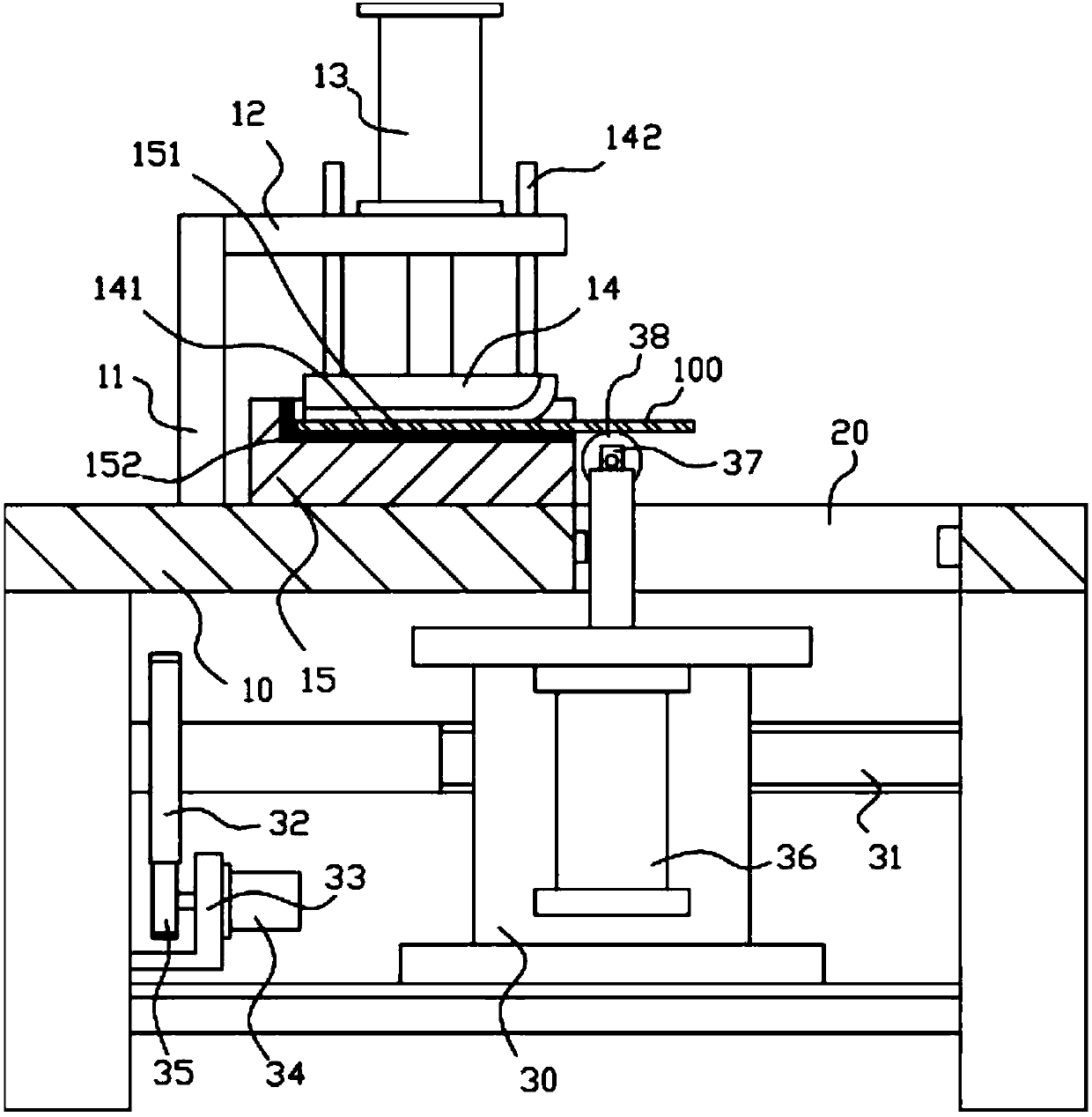
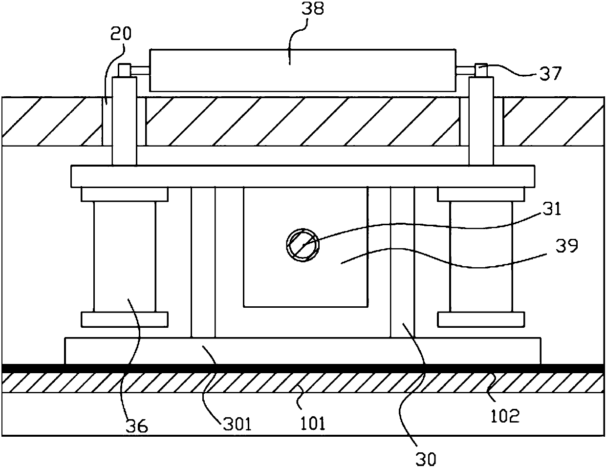
[0018] Example: see Figure 1 to Figure 2 As shown, a simple bending mechanism for metal sheets with adjustable pressure rollers includes a frame 10, a main support plate 11 is fixed in the middle of the top plate of the frame 10, and an upper inner wall of the top of the main support plate 11 is fixed. Support plate 12, the top surface of upper support plate 12 is fixed with compression oil cylinder 13, and the push rod of compression oil cylinder 13 passes upper support plate 12 and is fixed with main compression block 14, and the frame directly below upper support plate 12 A lower fixed block 15 is fixed on the top surface of the top plate of 10, and the middle part of the top surface of the lower fixed block 15 has a placement groove 151, and the right side of the placement groove 151 stretches out from the right side wall of the lower fixed block 15;

[0019] The bottom surface of the main pressing block 14 faces the placement groove 151;

[0020] Both sides of the right...


PUM


Abstract

The invention discloses a simple bending mechanism with an adjustable compression roller for hardware plates. The bending mechanism comprises a machine frame, wherein a main supporting plate is fixedin the middle part of a top plate of the machine frame; an upper supporting plate is fixed on the inner side wall of the top part of the main supporting plate, a pressing oil cylinder is fixed to thetop surface of the upper supporting plate, and a push rod of the pressing oil cylinder penetrates through the upper supporting plate and is fixedly provided with a main pressing block; a lower fixingblock is fixed to the top surface of the part, right below the upper supporting plate, of the top plate of the machine frame, a containing groove is formed in the middle part of the top surface of thelower fixing block, and the right side of the containing groove extends out of the right side wall of the lower fixing block; the bottom face of the main pressing block faces the containing groove; transverse through grooves are formed in the two sides of the middle part of the top plate of the machine frame; and a movable frame is in threaded connection with a transverse screw rod, two ends of the transverse screw rod are hinged to two side supporting plates arranged on the left side and the right side of the machine frame respectively, and a transmission gear is fixed to the left part of the transverse screw rod. The simple bending mechanism has the advantages that structure is simple, bending effect is good, the position of the compression roller can be adjusted according to needs, a bending part is not prone to be damaged, and effect is good.

Description

Technical field: [0001] The invention relates to the technical field of hardware component manufacturing equipment, and more specifically relates to a simple bending mechanism for metal sheet materials with adjustable pressure rollers. Background technique: [0002] Existing metal sheet materials such as steel plates need to be bent to a certain extent, and the existing bending mechanism is relatively complicated, and when bending, the bending position is easily damaged due to the sharp corners of the briquetting block, which affects the bending effect. Invention content: [0003] The purpose of the present invention is to address the deficiencies of the prior art, and to provide a simple bending mechanism for metal sheets with adjustable pressure rollers, which has a simple structure and good bending effect. It is not easy to be damaged, and the effect is good. [0004] Technical solutions of the present invention are as follows: [0005] A simple bending mechanism for ...

Claims


Application Information

Patent Timeline
Patent Type & Authority Applications(China)
IPC IPC(8): B21D5/04
Inventor 周建红
Owner FOSHAN BENJIEPU ELECTROMECHANICAL TECH CO LTD
Learn More