Supercharge Your Innovation With Domain-Expert AI Agents!

Injection mold for rotatably adjusting amount of glue inlet

A technology of rotation adjustment and injection mold, applied in the field of injection mold, can solve the problems of quality, processing efficiency, single adjustment of glue feeding amount, inconsistent speed of glue feeding point, etc., to achieve the effect of quality assurance

Inactive Publication Date: 2018-01-19
河北润昂密封材料有限公司
View PDF2 Cites 0 Cited by
  • Summary
  • Abstract
  • Description
  • Claims
  • Application Information

AI Technical Summary

Problems solved by technology

[0002] At present, for the injection molds of large plastic products, the gating system of the injection molds often adopts multi-point glue feeding, so as to achieve simultaneous glue feeding everywhere and improve the injection molding efficiency. The runners generally take the main channel to each inlet The shortest distance between the glue points can save materials, but due to the multi-point glue injection, this will make the speed of each glue point inconsistent, which will lead to inconsistent pressure and glue injection in the cavity, which often leads to problems in the injection molding process. The lack of material, burnt and other poor appearance of the product and the ejection problem caused by the excessive tightness of the product due to partial overfilling, so the injection speed (that is, the amount of glue) has a great influence on the quality of the product and the efficiency of processing. However, on the current injection mold, the single adjustment of the amount of glue

Method used


Image

  • Injection mold for rotatably adjusting amount of glue inlet
  • Injection mold for rotatably adjusting amount of glue inlet
  • Injection mold for rotatably adjusting amount of glue inlet

Examples


Embodiment Construction

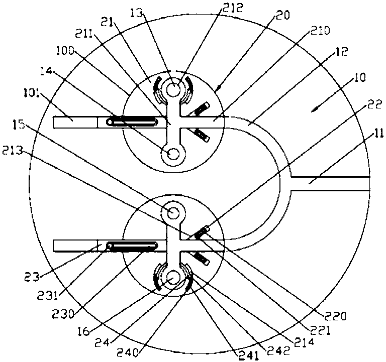
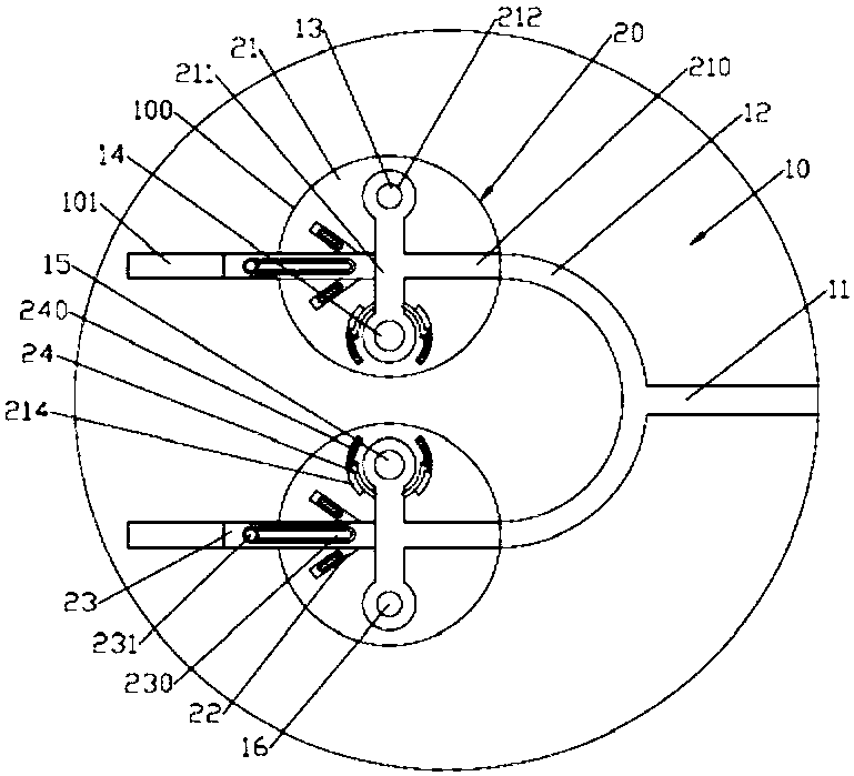
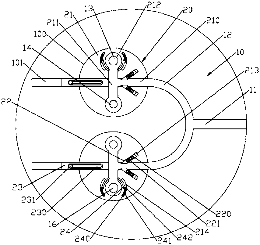
[0014] Such as figure 1 , image 3 As shown, an injection mold for rotating and adjusting the amount of glue, including a mold body 10; the surface of the mold body 10 is formed with a main channel 11 arranged in the left and right directions; the left end of the main channel 11 is connected with a central arc-shaped flow channel 12; the mold body The surface of 10 is formed with a pair of symmetrical cylindrical groove-shaped rotary adjustment grooves 100; the right side of the rotary adjustment groove 100 communicates with the left end of the central arc-shaped flow channel 12; the left side wall of the rotary adjustment groove 100 is formed with a rectangular The limit blocking groove 101; the rotation adjustment groove 100 is provided with a rotation adjustment device 20; the rotation adjustment device 20 includes a cylindrical rotation adjustment block 21; the upper end surface of the rotation adjustment block 21 is formed with a left and right through horizontal passage ...


PUM


Abstract

The invention discloses an injection mold for rotatably adjusting the amount of glue inlet. The injection mold includes a mold body. The surface of the mold body is rotationally provided with a pair of rotatable adjusting blocks which are symmetrical front and back. A left-right penetrating horizontal passing slot and a front-back vertical passing slot are formed in the upper end surface of each rotatable adjusting block. The centers of each vertical passing slot and the corresponding horizontal passing slot are crossed and communicate with each other. Cylindrical-groove-shaped glue inlet holes are formed in the bottom surfaces of the front and back ends of each vertical passing slot. The pair of glue inlet holes in the front side communicates with a first flow channel and a second flow channel correspondingly. The pair of glue inlet holes in the back side communicates with a third flow channel and a fourth flow channel correspondingly. A limiting and blocking groove is internally andslidably provided with limiting and blocking blocks left and right. Arc-shaped adjusting strips are correspondingly arranged on the left side wall and the right side wall of the ends, away from each other, of the pair of vertical passing slots. Oblique adjusting blocks are correspondingly arranged on the front side wall and the back side wall of the right part of each horizontal passing slot. Theinjection mold can effectively adjust the amount of glue materials passing through each flow channel to be injected into a mold forming cavity and ensures the quality of product forming.

Description

technical field [0001] The invention relates to the technical field of injection molds, in particular to an injection mold for adjusting the amount of glue fed by rotation. Background technique [0002] At present, for the injection molds of large plastic products, the gating system of the injection molds often adopts multi-point glue feeding, so as to achieve simultaneous glue feeding everywhere and improve the injection molding efficiency. The runners generally take the main channel to each inlet The shortest distance between the glue points can save materials, but due to the multi-point glue injection, this will make the speed of each glue point inconsistent, which will lead to inconsistent pressure and glue injection in the cavity, which often leads to problems in the injection molding process. The lack of material, burnt and other poor appearance of the product and the ejection problem caused by the excessive tightness of the product due to partial overfilling, so the i...

Claims


Application Information

Patent Timeline
Patent Type & Authority Applications(China)
IPC IPC(8): B29C45/30
Inventor 徐亚维
Owner 河北润昂密封材料有限公司
Features
  • R&D
  • Intellectual Property
  • Life Sciences
  • Materials
  • Tech Scout
  • Unparalleled Data Quality
  • Higher Quality Content
  • 60% Fewer Hallucinations
Learn More