Supercharge Your Innovation With Domain-Expert AI Agents!

Injection mold with glue feeding amount manual adjusting device

A manual adjustment and injection mold technology, applied in the field of injection molds, can solve the problems of quality, processing efficiency, inconsistencies in pressure and glue injection, and tightness of products with poor appearance, so as to achieve the effect of quality assurance

Inactive Publication Date: 2018-03-20
DONGGUAN LIANZHOU INTPROP OPERATION MANAGEMENT CO LTD
View PDF5 Cites 2 Cited by
  • Summary
  • Abstract
  • Description
  • Claims
  • Application Information

AI Technical Summary

Problems solved by technology

[0002] At present, for the injection molds of large plastic products, the gating system of the injection molds often adopts multi-point glue feeding, so as to achieve simultaneous glue feeding everywhere and improve the injection molding efficiency. The runners generally take the main channel to each inlet The shortest distance between the glue points can save materials, but due to the multi-point glue injection, this will make the speed of each glue point inconsistent, which will lead to inconsistent pressure and glue injection in the cavity, which often leads to problems in the injection molding process. The lack of material, burnt and other poor appearance of the product and the ejection problem caused by the excessive tightness of the product due to partial overfilling, so the injection speed (that is, the amount of glue) has a great influence on the quality of the product and the efficiency of processing. However, on the current injection mold, the single adjustment of the amount of glue

Method used


Image

  • Injection mold with glue feeding amount manual adjusting device
  • Injection mold with glue feeding amount manual adjusting device
  • Injection mold with glue feeding amount manual adjusting device

Examples


Embodiment Construction

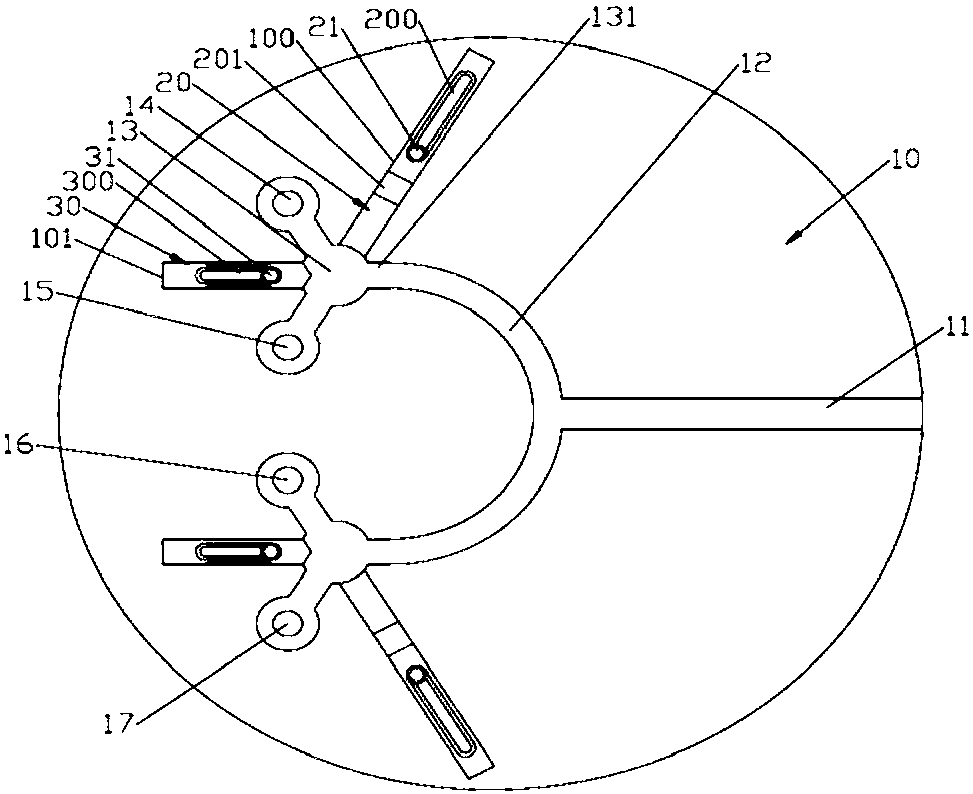
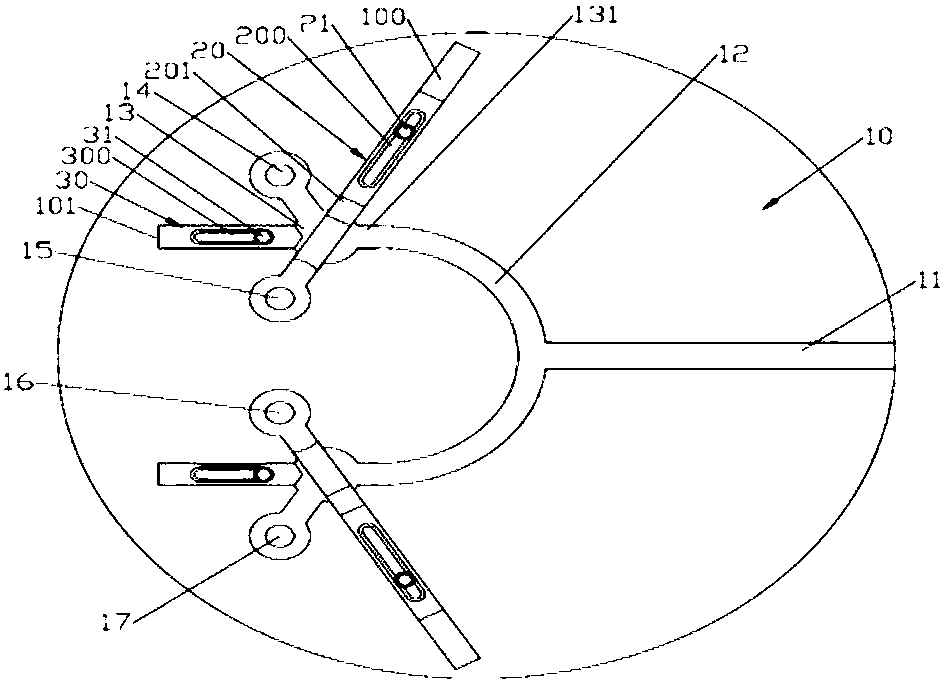
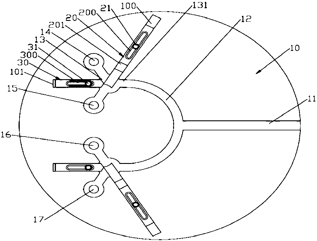
[0014] like Figure 1 ~ Figure 3 As shown, an injection mold with a manual adjustment device for glue injection includes a mold body 10; the surface of the mold body 10 is formed with a main channel 11 arranged in a left and right direction; the left end of the main channel 11 is connected with a central arc-shaped flow channel 12; The surface of the mold body 10 is formed with a pair of front and rear symmetrical adjustment flow channel units; the adjustment flow channel unit is composed of a cylindrical groove-shaped central groove 13 and three runners 131 uniformly distributed on the side wall of the central groove 13; the right side The direction of the flow channel 131 is set to the right; the front and rear ends of the central arc-shaped flow channel 12 communicate with the flow channel 131 on the right side of a pair of regulating flow channel units respectively; The channel 131 communicates with the first branch channel 14 and the second branch channel 15 respectively;...


PUM


Abstract

The invention discloses an injection mold with a glue feeding amount manual adjusting device. The injection mold comprises a mold body; a pair of front and back symmetric adjusting flow channel unitsare formed on the surface of the mold body; the adjusting flow channel units are composed of cylindrical groove-shaped central grooves and three diversion channels evenly distributed on the side wallsof the central grooves in circumference; the two diversion channels on the left side of the adjusting flow channel unit on the front side of the mold body communicate with the a first branch channeland a second branch channel; the two diversion channels on the left side of the adjusting flow channel unit on the rear side of the mold body communicate with a third branch channel and a fourth branch channel; flow equalizing adjusting blocks are arranged on the side walls of the central grooves right opposite to the diversion channels on the right sides of the mold body in a sliding mode; rubbermaterial adjusting blocks are arranged on the side walls of the central grooves right opposite to the diversion channels communicating with the second branch flow channel and the third branch flow channel; and the sliding direction of the rubber material adjusting blocks is the same as the direction of the diversion channels right opposite to the rubber material adjusting blocks in the positive direction. According to the injection mold, the amount of rubber material injected into a mold cavity through all diversion channels can be effectively adjusted, so that quality of product forming is guaranteed.

Description

technical field [0001] The invention relates to the technical field of injection molds, in particular to an injection mold with a manual adjustment device for glue feeding. Background technique [0002] At present, for the injection molds of large plastic products, the gating system of the injection molds often adopts multi-point glue feeding, so as to achieve simultaneous glue feeding everywhere and improve the injection molding efficiency. The runners generally take the main channel to each inlet The shortest distance between the glue points can save materials, but due to the multi-point glue injection, this will make the speed of each glue point inconsistent, which will lead to inconsistent pressure and glue injection in the cavity, which often leads to problems in the injection molding process. The lack of material, burnt and other poor appearance of the product and the ejection problem caused by the excessive tightness of the product due to partial overfilling, so the i...

Claims


Application Information

Patent Timeline
Patent Type & Authority Applications(China)
IPC IPC(8): B29C45/30
CPCB29C45/30B29C2045/306
Inventor 徐亚维
Owner DONGGUAN LIANZHOU INTPROP OPERATION MANAGEMENT CO LTD
Features
  • R&D
  • Intellectual Property
  • Life Sciences
  • Materials
  • Tech Scout
  • Unparalleled Data Quality
  • Higher Quality Content
  • 60% Fewer Hallucinations
Learn More