
Drag reducing and speed increasing pipeline with microporous inner wall

A pipeline and microporous technology, applied in the direction of mechanical equipment, fluid flow, etc., can solve the problems of unsuitable environment for single-phase flow, weakening, and destruction of microbubbles.

Active Publication Date: 2018-01-19
CHANGZHOU UNIV
View PDF7 Cites 3 Cited by
  • Summary
  • Abstract
  • Description
  • Claims
  • Application Information

AI Technical Summary

Problems solved by technology

However, as the working time increases, the microbubbles are destroyed, so the effect of reducing adhesion gradually weakens
However, the method of adding air bubbles to the liquid phase fluid is not suitable for some environments that have special requirements for single-phase flow.

Method used


Image

  • Drag reducing and speed increasing pipeline with microporous inner wall
  • Drag reducing and speed increasing pipeline with microporous inner wall
  • Drag reducing and speed increasing pipeline with microporous inner wall

Examples


Embodiment Construction

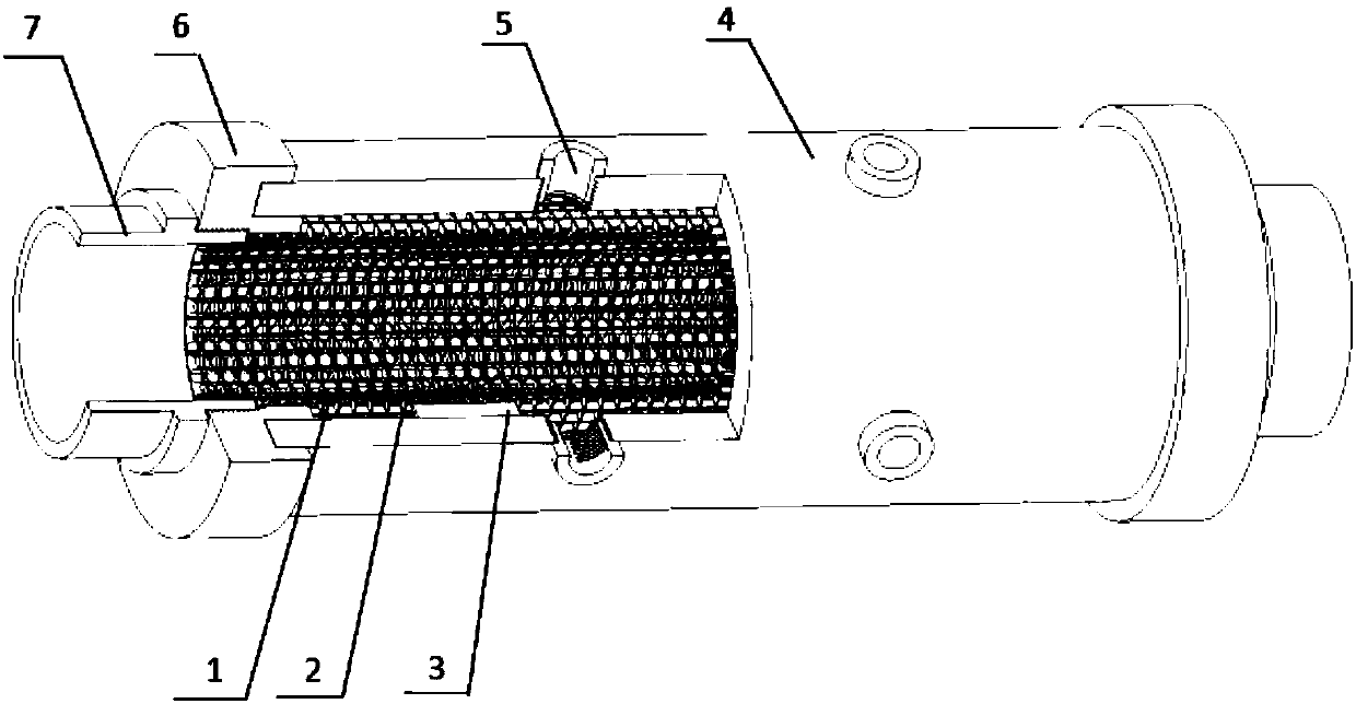
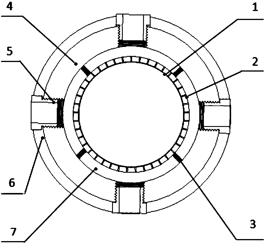
[0024] Embodiments of the present invention will be described in detail below in conjunction with the accompanying drawings. Such as figure 1 The invention shown is a pipe that regulates the flow rate and pressure of fluid within the pipe. Including: porous inner sleeve 1, stencil support sleeve 2, support body 3, outer sleeve 4, pneumatic joint 5, flange 6, pipe joint 7.

[0025] The porous inner sleeve 1 is the main part in contact with the fluid, and forms a micro-air chamber on the inner wall of the pipeline. The gas-liquid two-phase contact reduces the pressure loss on the wall compared with the single-phase contact of the liquid phase. The outer wall surface of the porous inner sleeve 1 is adhered to the mesh support sleeve 2, and the two form a nested structure. Micro-square holes are evenly distributed on the screen support sleeve 2 . A plurality of rectangular support bodies 3 are adhered to the outer wall surface of the screen support sleeve 2 . The support body ...


PUM


Abstract

The invention belongs to the field of drag reducing and speed increasing pipelines, and specifically relates to a drag reducing and speed increasing pipeline with a microporous inner wall. The drag reducing and speed increasing pipeline is characterized in that a special microporous inner wall structure is adopted; micro-bubbles are captured through the micropores in the inner wall of the pipeline, and a solid-liquid interface is replaced by an air-liquid interface, thus the adhering effect of liquid and the inner wall of the pipeline can be reduced, and as a result, the drag reducing and speed increasing effects can be achieved; meanwhile, the additional pressure of the micropores is regulated, and the lost micro-bubbles are timely supplemented, so that the air-liquid contact can be keptcontinuous and stable, and as a result, the drag reducing and speed reducing effects can be valid within long working time.

Description

technical field [0001] The invention belongs to the field of drag-reducing and speed-up pipelines, in particular to a drag-reducing and speed-up pipeline with microporous inner walls. Background technique [0002] Due to the adhesion between the viscous fluid and the wall of the pipe flowing through it, energy loss will occur along the way of the fluid, resulting in a decrease in parameters such as pressure and velocity. This phenomenon is more pronounced for pipes with longer lengths or smaller diameters. To reduce this energy loss, reducing the effect of fluid adhesion on the wall is the key. Commonly used methods include using a pipe with a smoother inner wall, making a hydrophobic or oleophobic bionic microstructure on the inner wall of the pipe, adding gas to the fluid to form a bubbly fluid, and so on. Among them, reducing the adhesion work between the fluid and the pipeline is the key. Generally, the work of adhesion between a gas and a liquid is significantly smal...

Claims


Application Information

Patent Timeline
Patent Type & Authority Applications(China)
IPC IPC(8): F15D1/02F15D1/06
Inventor 坎标高运丁建宁李征宇徐盛松
Owner CHANGZHOU UNIV
Learn More